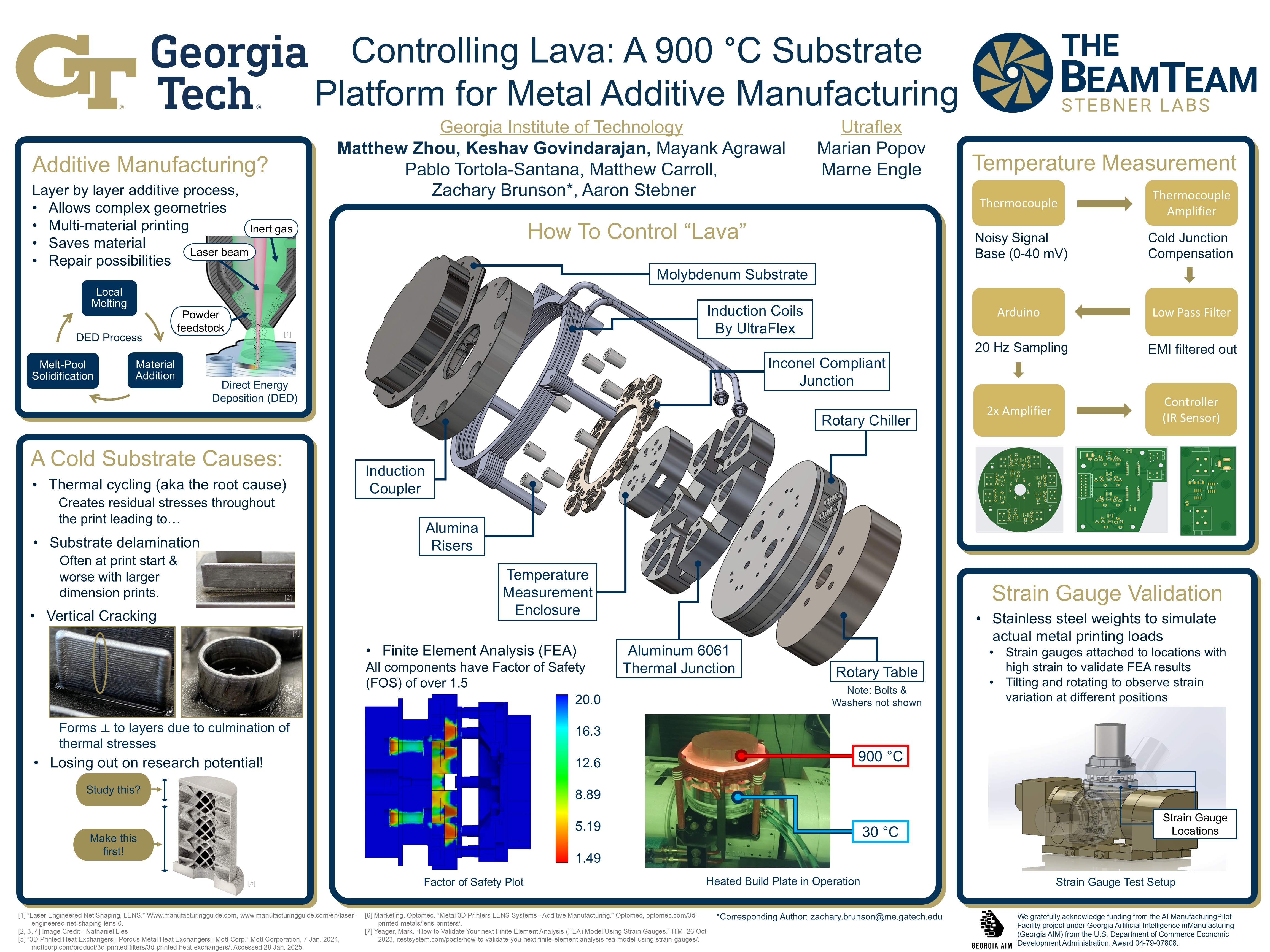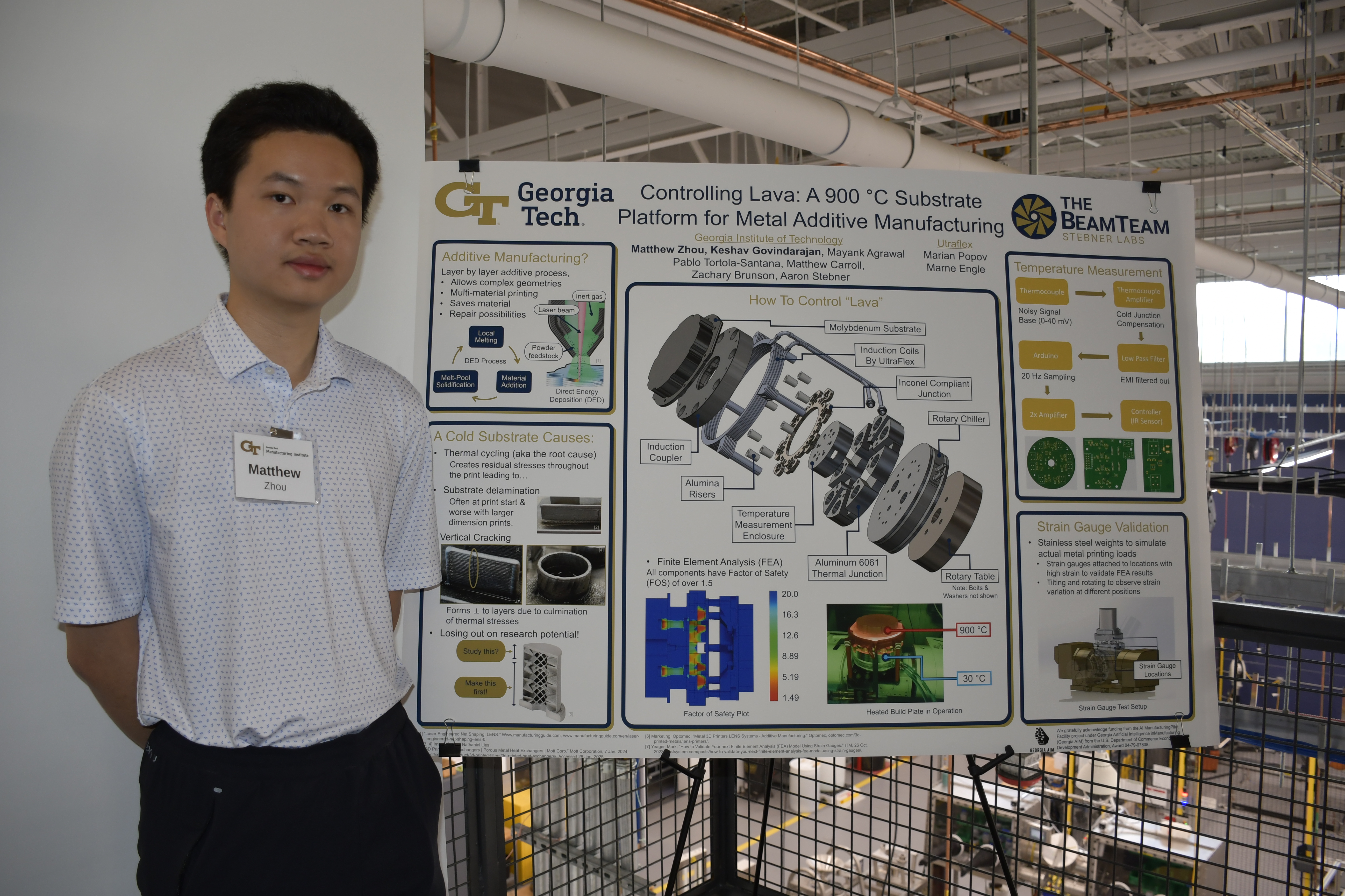

Metal 3D Printing Heated Build Plate Validation
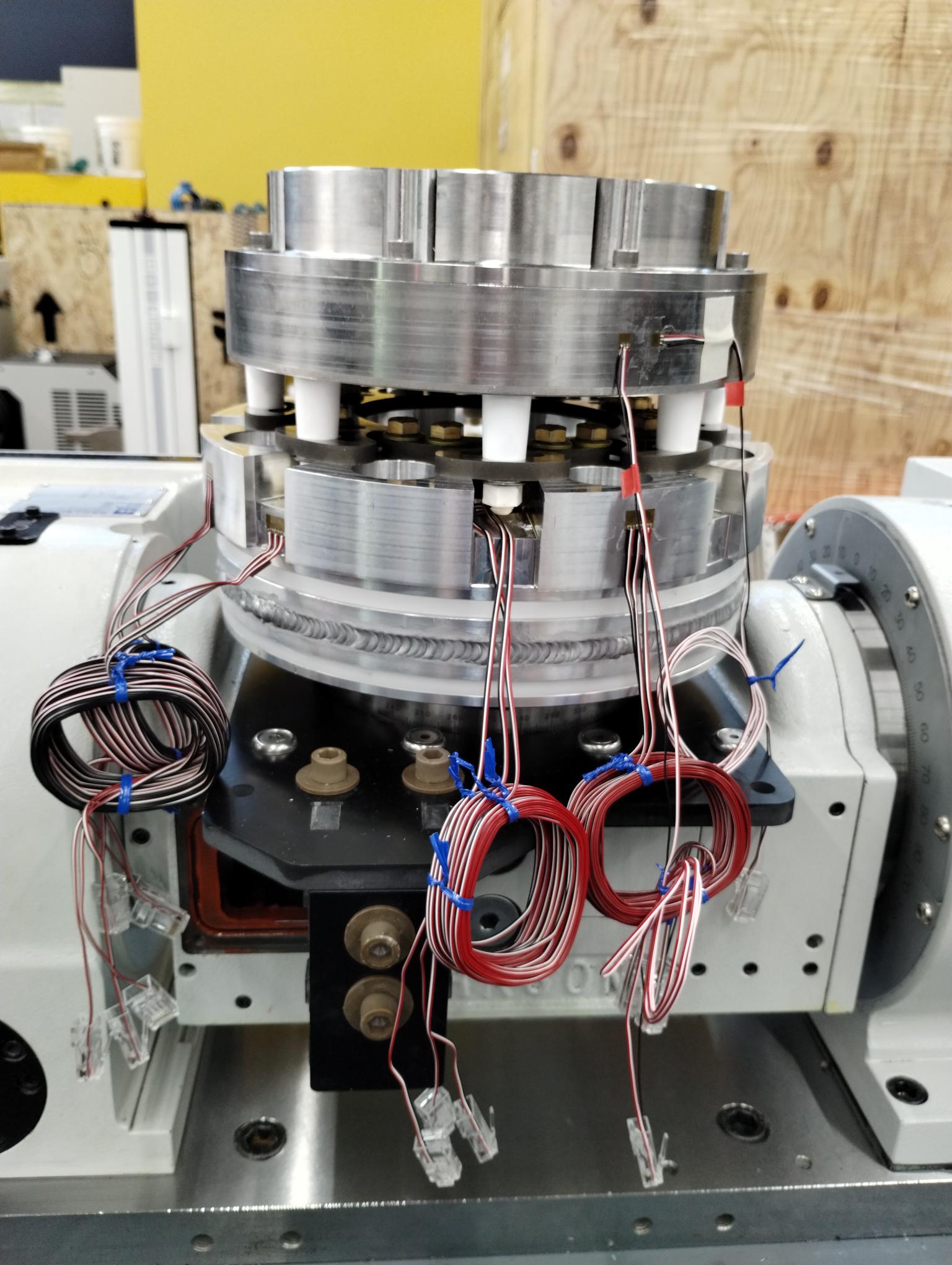
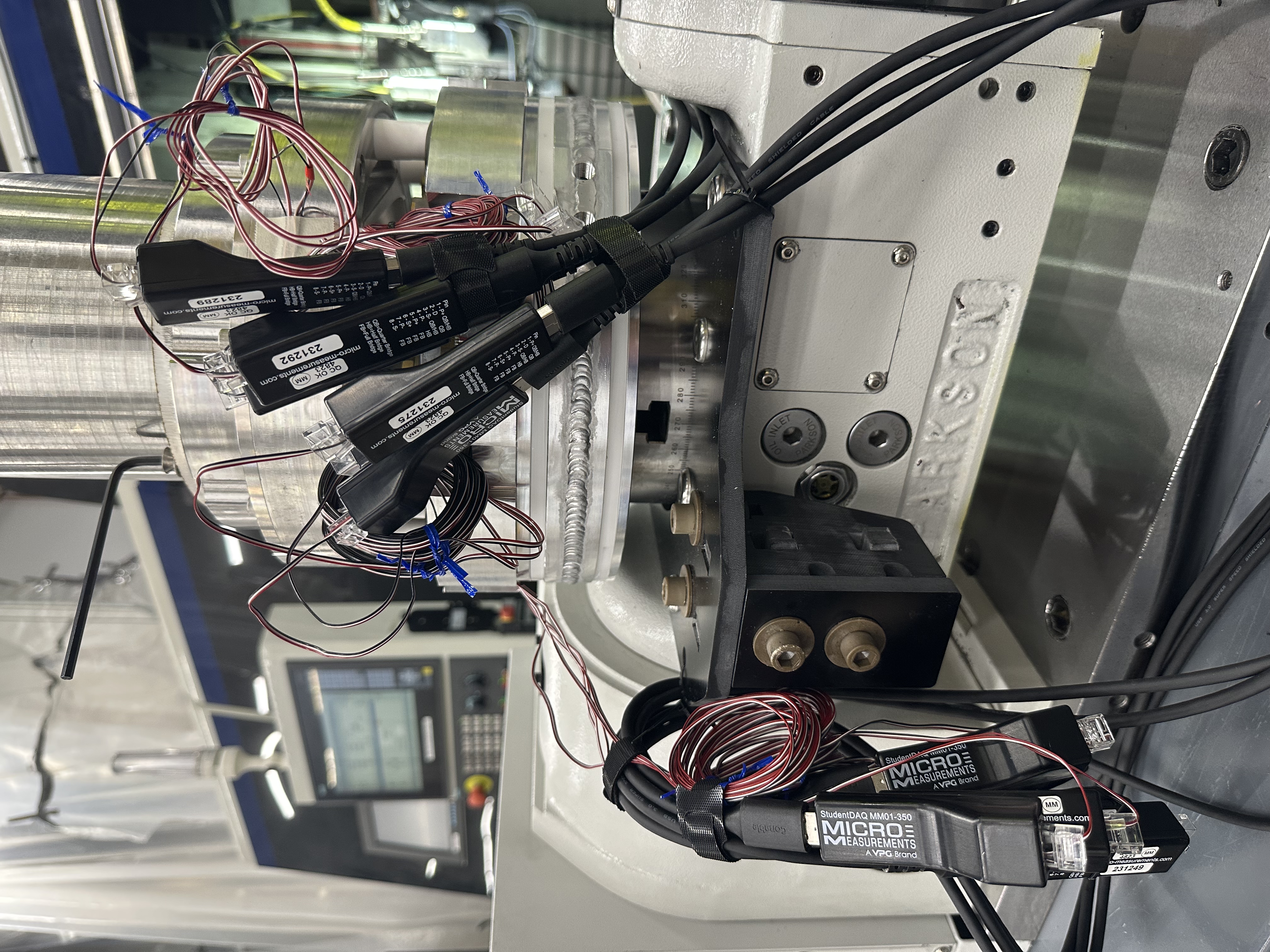
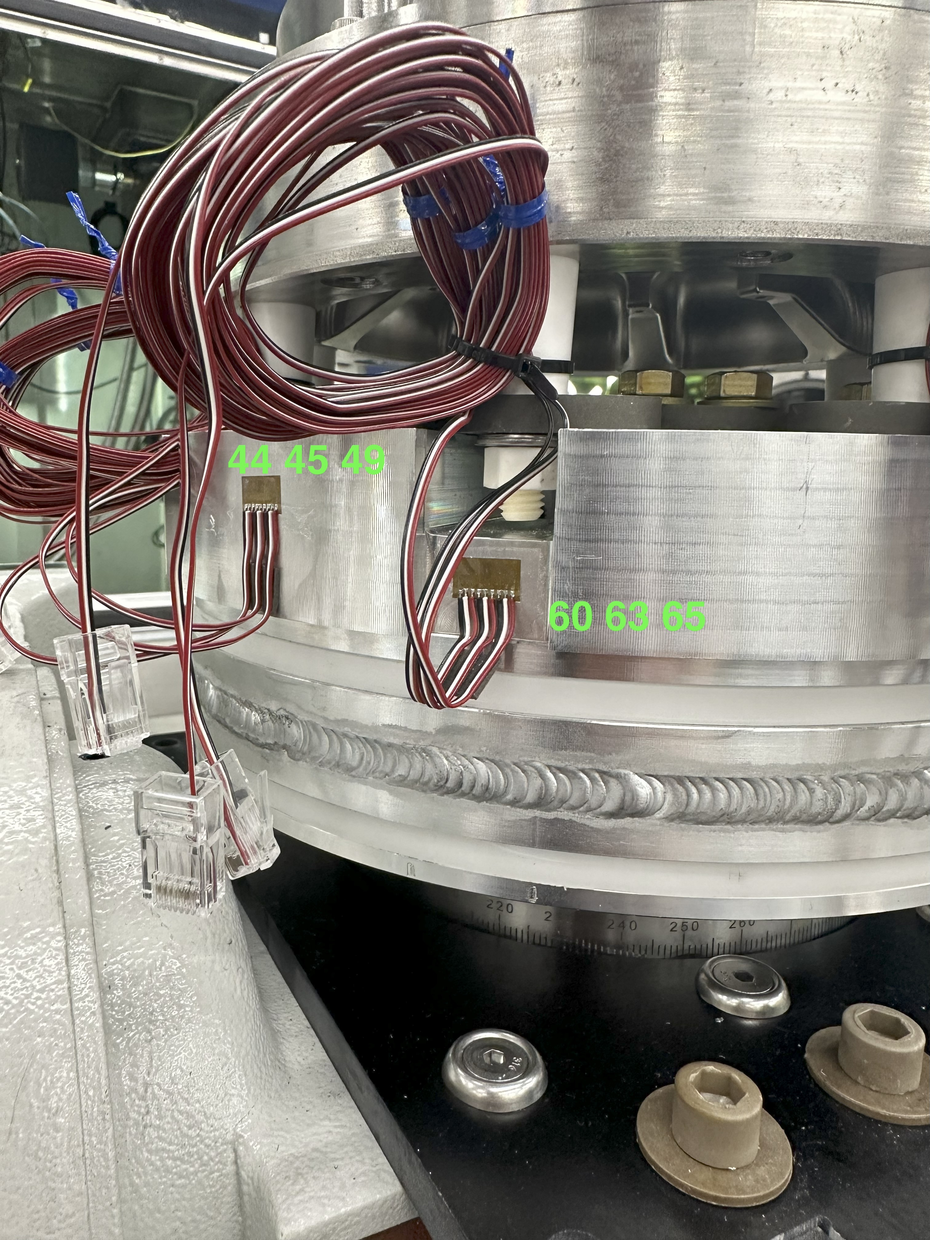
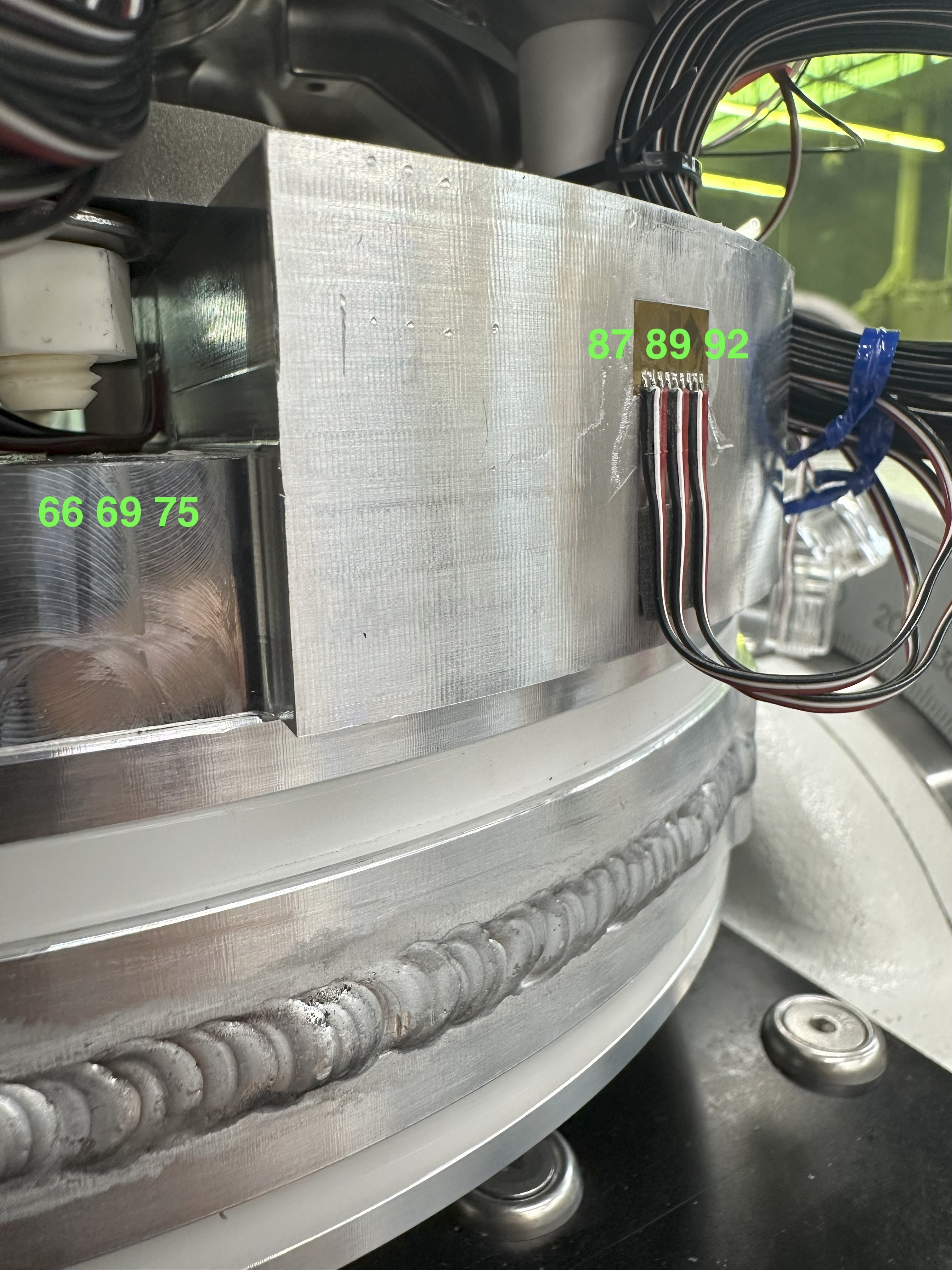
Validated the design through FEA and cold testing using machined stainless-steel weights and hand-soldered strain gauges.
Introduction
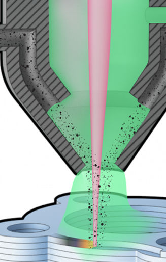
Directed Energy Deposition (DED) is a metal additive manufacturing process in which metallic feedstock is delivered into a localized melt pool created by a concentrated heat source, typically a laser. As the melt pool moves, new materials are deposited and solidifies layer by layer, allowing DED to build complex metal geometries, add multiple materials, and repair or modify existing components. Unlike many conventional manufacturing processes, DED repeatedly heats a small region of material to very high temperature while the surrounding part and substrate remain much cooler. Each deposited layer therefore experiences a severe heating-and-cooling cycle.
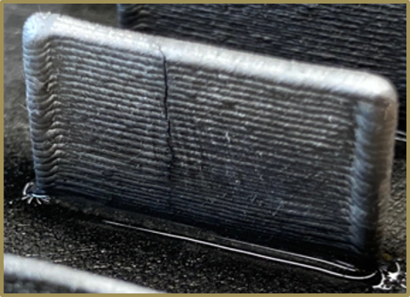
These repeated thermal cycles can generate large temperature gradients and corresponding residual stress throughout a print. On a cold substrate, the first deposited layers cool particularly rapidly, while later layers repeatedly reheat the material below them. The resulting thermal mismatch can cause the printed material to pull away from the substrate, especially at the beginning of a build or as the footprint of the part becomes larger. Residual stress can also accumulate through successive layers and produce vertical cracking through the printed component. These effects not only reduce print quality and reliability but also restrict the range of geometries, materials, and thermal conditions that can be investigated experimentally.
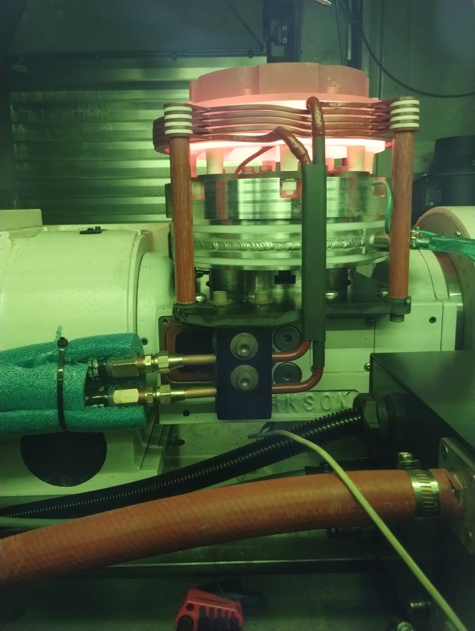
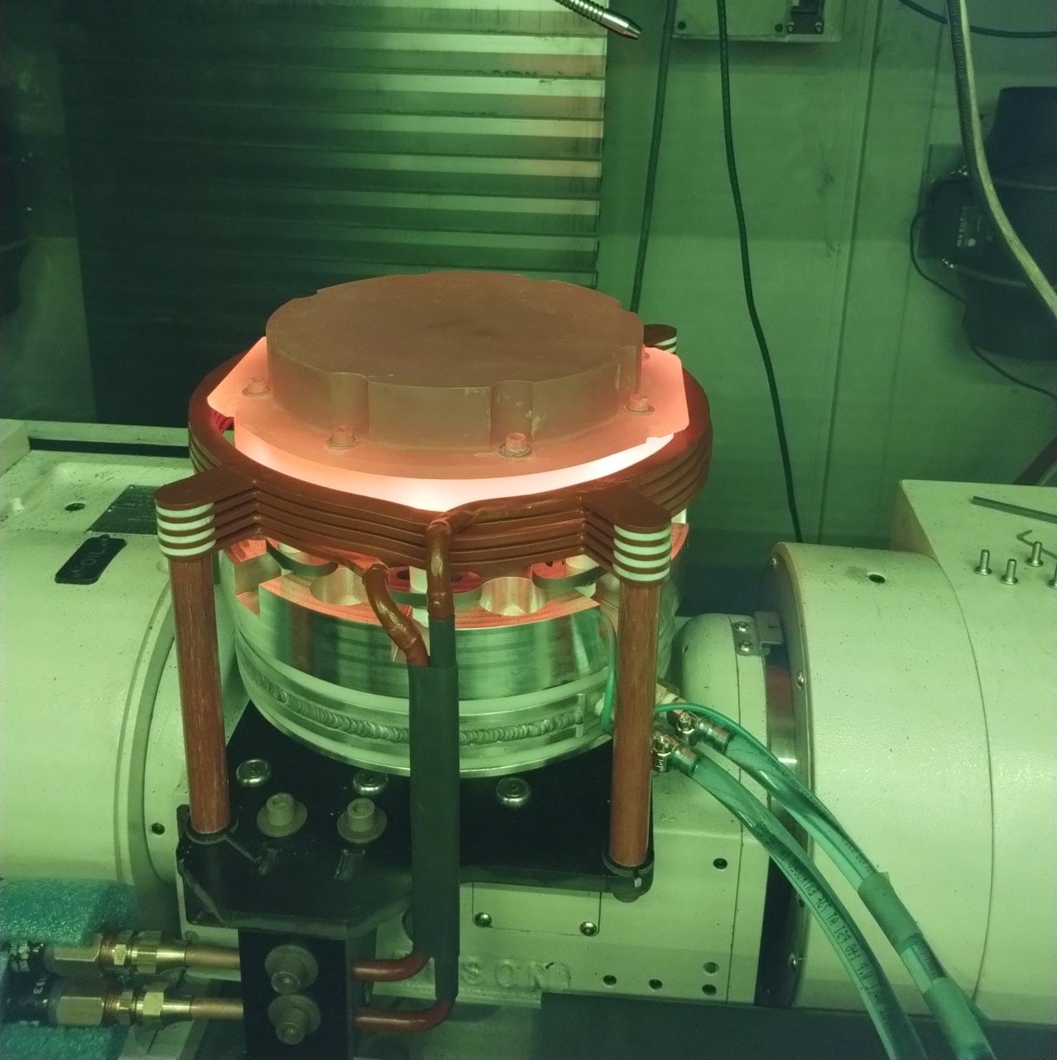
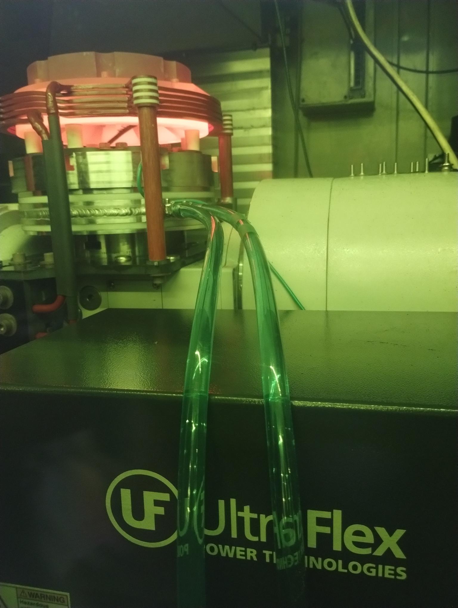
The heated build plate project was developed to address this problem by controlling the temperature of the substrate during DED. The system was designed to heat the build substrate to up to 900 °C while thermally isolating it from the much cooler rotary stage beneath it. The assembly combines a high temperature build substrate with induction heating, insulating and compliant structural elements, cooling hardware, and temperature sensing, while retaining the rotary and tilt motion required for multi-axis printing.
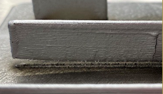
Maintaining an elevated substrate temperature reduces the temperature difference between newly deposited material and the existing structure, providing a way to control cooling rate, alleviate thermal cycling, and improve print quality.
By the time I joined the project, the core mechanical design had already been developed, and the major components had been fabricated. Previous researchers had spent approximately two years developing the mechanical, thermal, and electrical architecture of the system. Finite-element models were also underway to evaluate the structure under both mechanical and thermal loading. However, experimental validation was needed before their predictions could be relied upon.
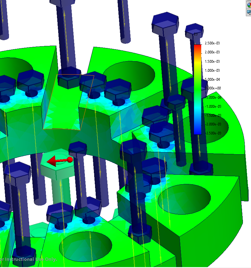
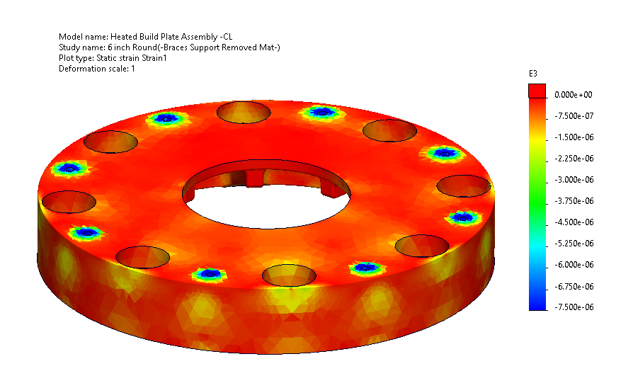
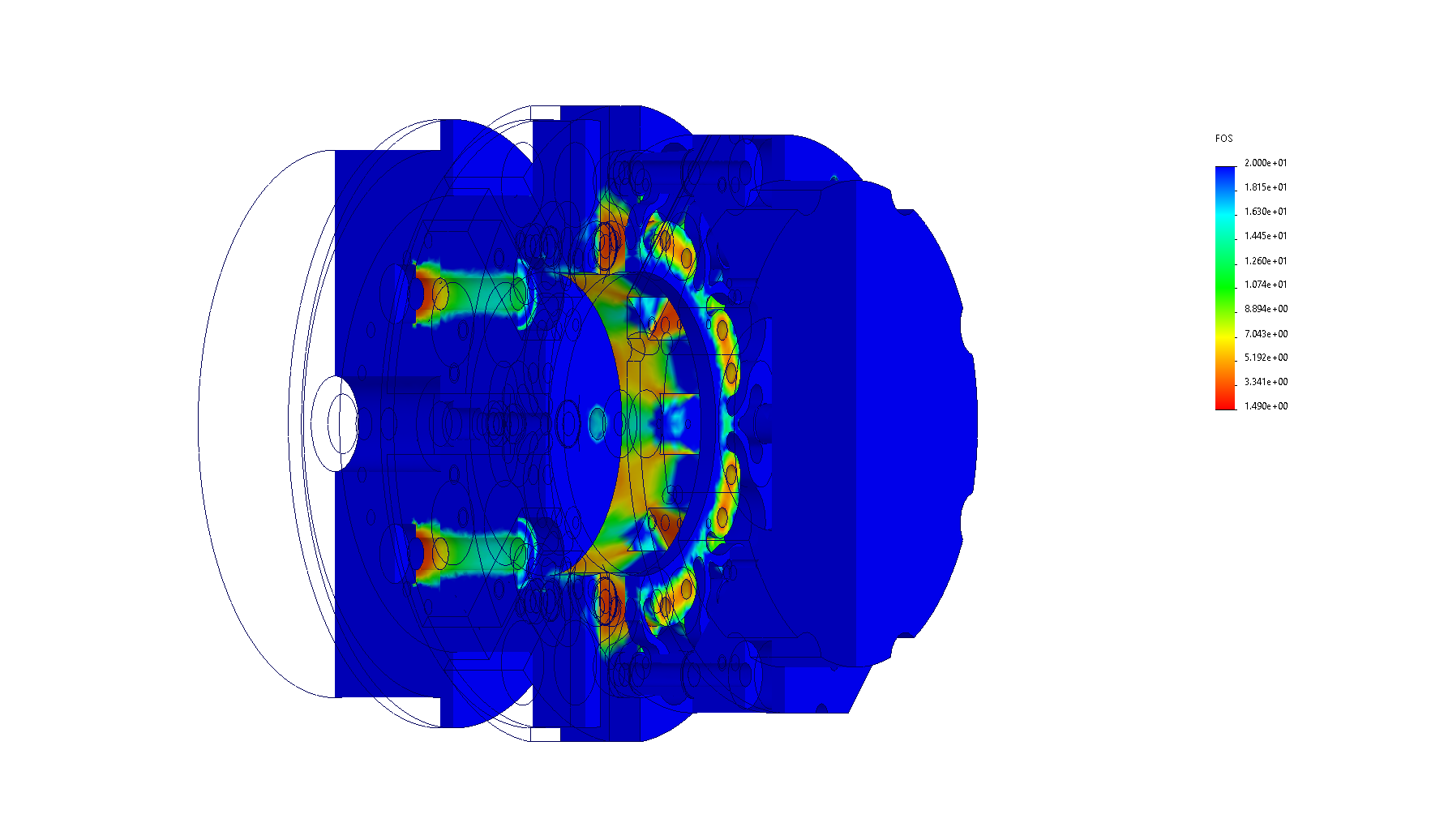
My main objective was to determine whether the actual structure behaved in the way predicted by the finite-element model. The planned validation used representative weights to reproduce the mechanical loading of a large metal print and strain gauges placed at locations where the simulation predicted relatively high strain. The system could then be tilted and rotated so that measured strain could be compared against the simulated load cases. I focused on turning that validation concept into a practical experiment: first developing a simple proof-of-concept loading test, then designing a repeatable cold structural test using machined stainless-steel weights and strain gauges and finally comparing the measured strain response against the FEA predictions.
Methodology
A strain gauge consists of a thin conductive grid bonded to a flexible backing. When the surface beneath the gauge stretches or contracts, the grid deforms with it, producing a proportional resistance change that can be measured through a bridge circuit and converted into strain. Because the gauges respond to deformation of the surface they are bonded to, the quality of the installation is critical: poor adhesion, contamination, misalignment, or damaged solder joints can produce errors in the strain readings.
Installing the gauges required careful surface preparation and handling. The selected measurement area was first cleaned and degreased, then lightly abraded to remove surface oxidation and provide a consistent bonding surface. The area was then cleaned and chemically conditioned before the gauge was aligned with the intended measurement direction and bonded using adhesive.
For locations where the strain direction was not known in advance, a three-element strain-gauge rosette was used. It combines three gauges at different angles and allows a two-dimensional surface strain state to be reconstructed. The measured strains can be related through the planar strain transformation
The strain state can therefore be represented by the tensor
where \(\gamma_{xy}=2\varepsilon_{xy}\). With measurements from the three known gauge orientations, the unknown \(\varepsilon_x\), \(\varepsilon_y\), and \(\gamma_{xy}\) can be solved and subsequently converted into principal strains or compared directly with the strain components predicted by FEA.
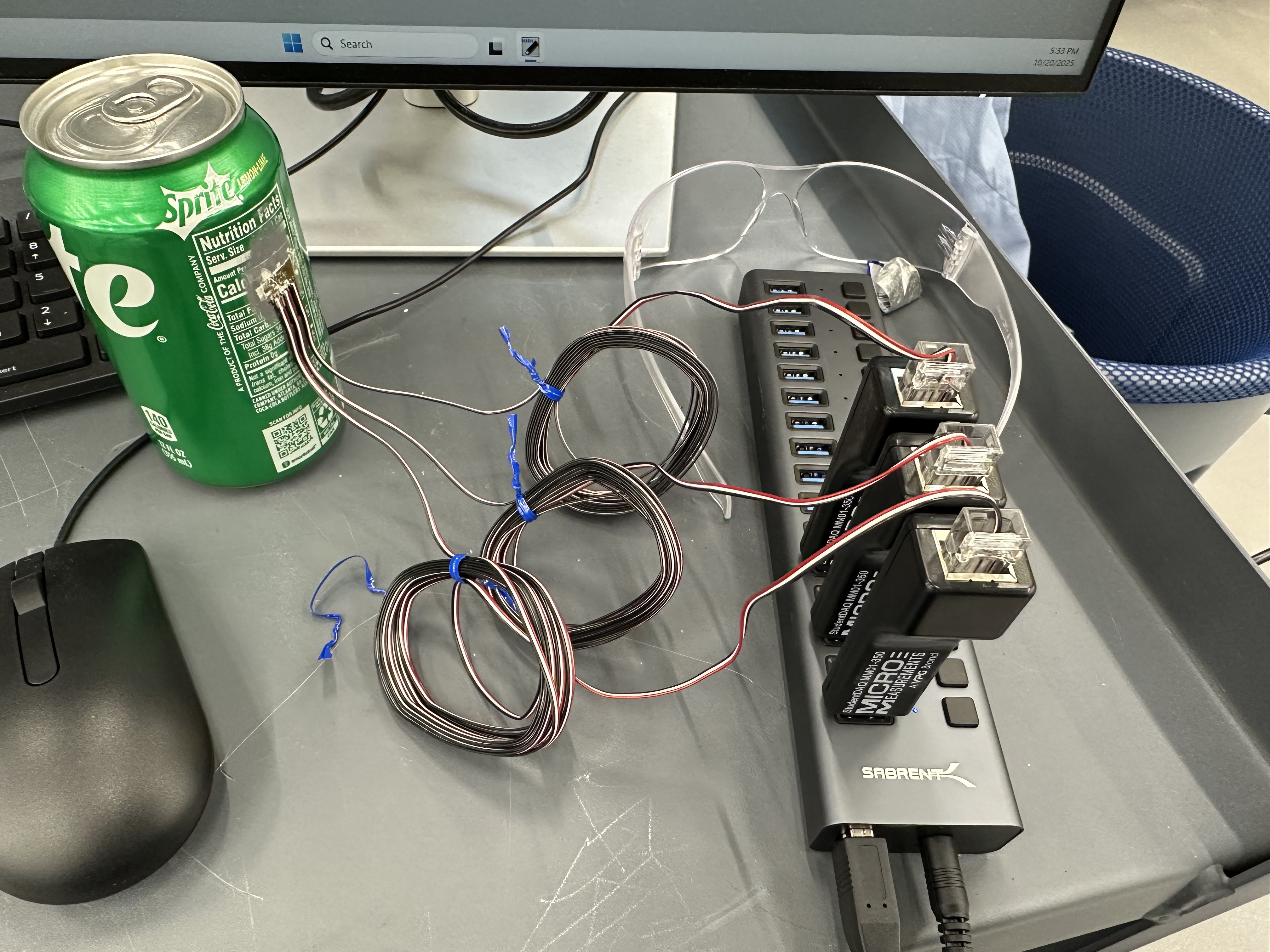
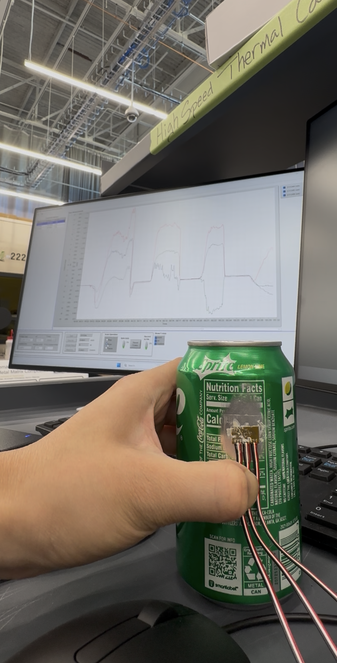
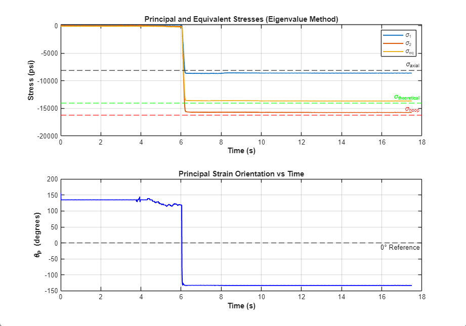
Before attaching gauges to the heated build plate, I first performed a soda-can test to verify that mounting, soldering, acquisition, and strain-reduction procedure could produce credible measurements. A sealed aluminum beverage can provide a useful calibration experiment because it behaves exactly as a thin-walled pressure vessel whose mechanical response is well understood. The known internal pressure creates circumferential (hoop) stress and longitudinal stress. For a cylindrical thin-walled vessel,
This test can provide a much more controlled validation case than immediately testing the complex build-plate assembly and potentially ruining the parts and wasting strain gauges.
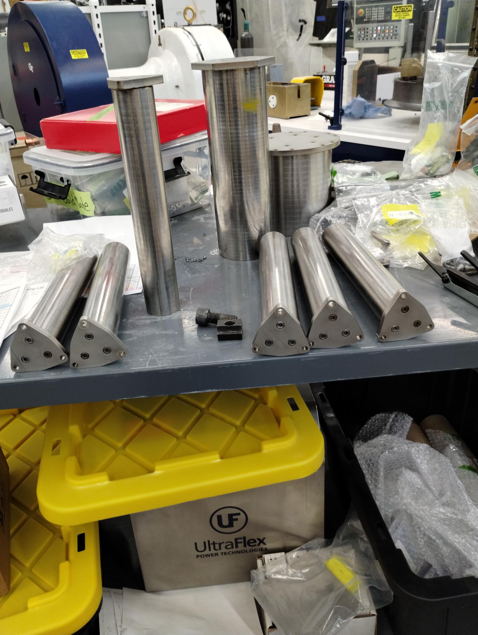
The cold test was then designed to validate the structural FEA of the heated build plate. To reproduce the mechanical effect of a large printed component, I designed a set of machined stainless-steel weights and mounting hardware. The loading system used multiple cylindrical masses that could be attached at controlled positions on the build surface with the most severe configuration placing the load toward the outer radius of the plate, intentionally generating a larger bending moment for a worst-case loading condition.
The assembled platform would first be measured in an unloaded reference condition, after which the known masses would be installed. The trunnion would then be tilted and rotated through multiple orientations, changing the direction of gravity relative to the structure and providing several load cases from a single physical setup and allowed the measured strain at each orientation to be compared directly with the corresponding FEA prediction.
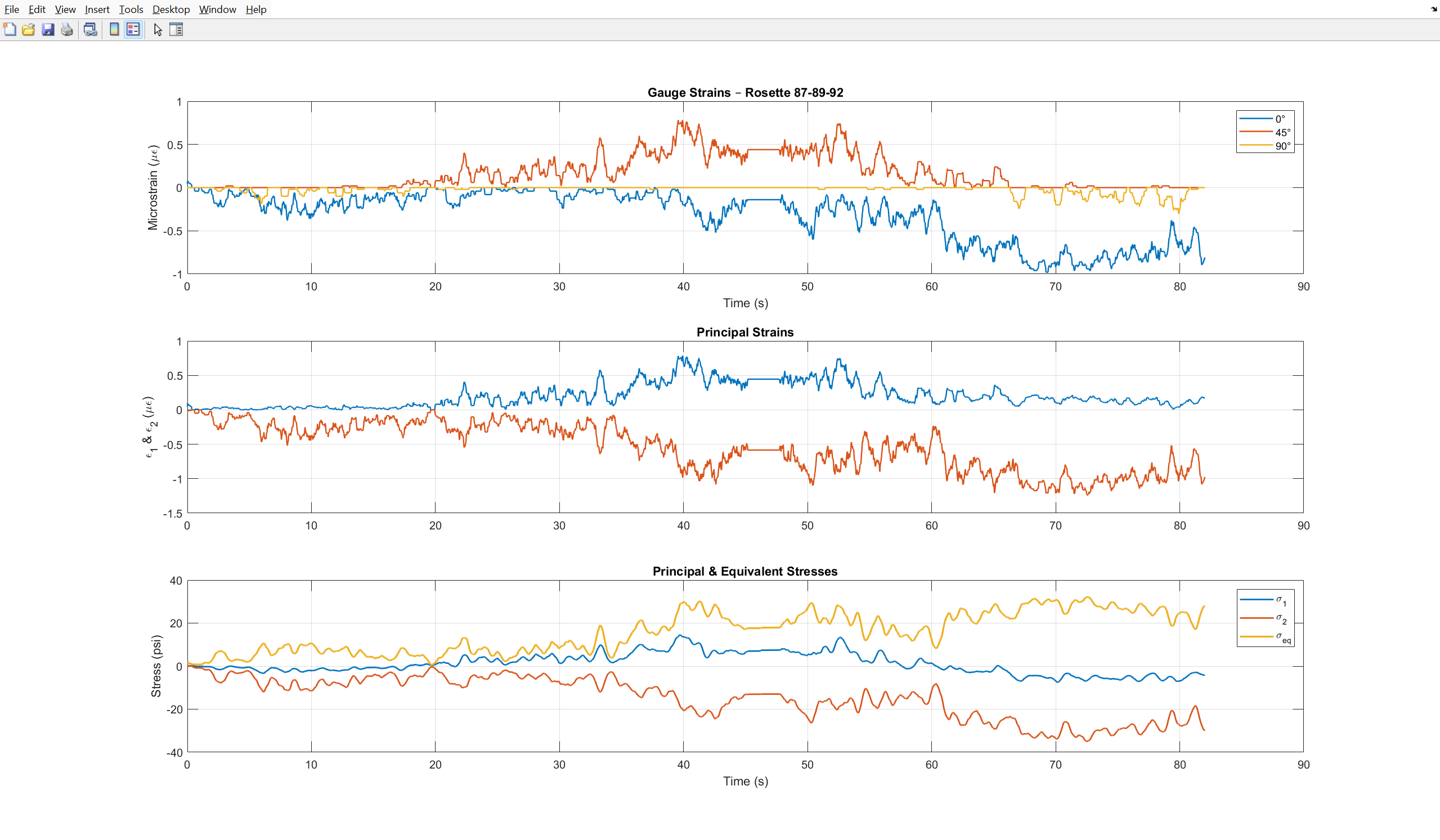
Soda Can Test Results
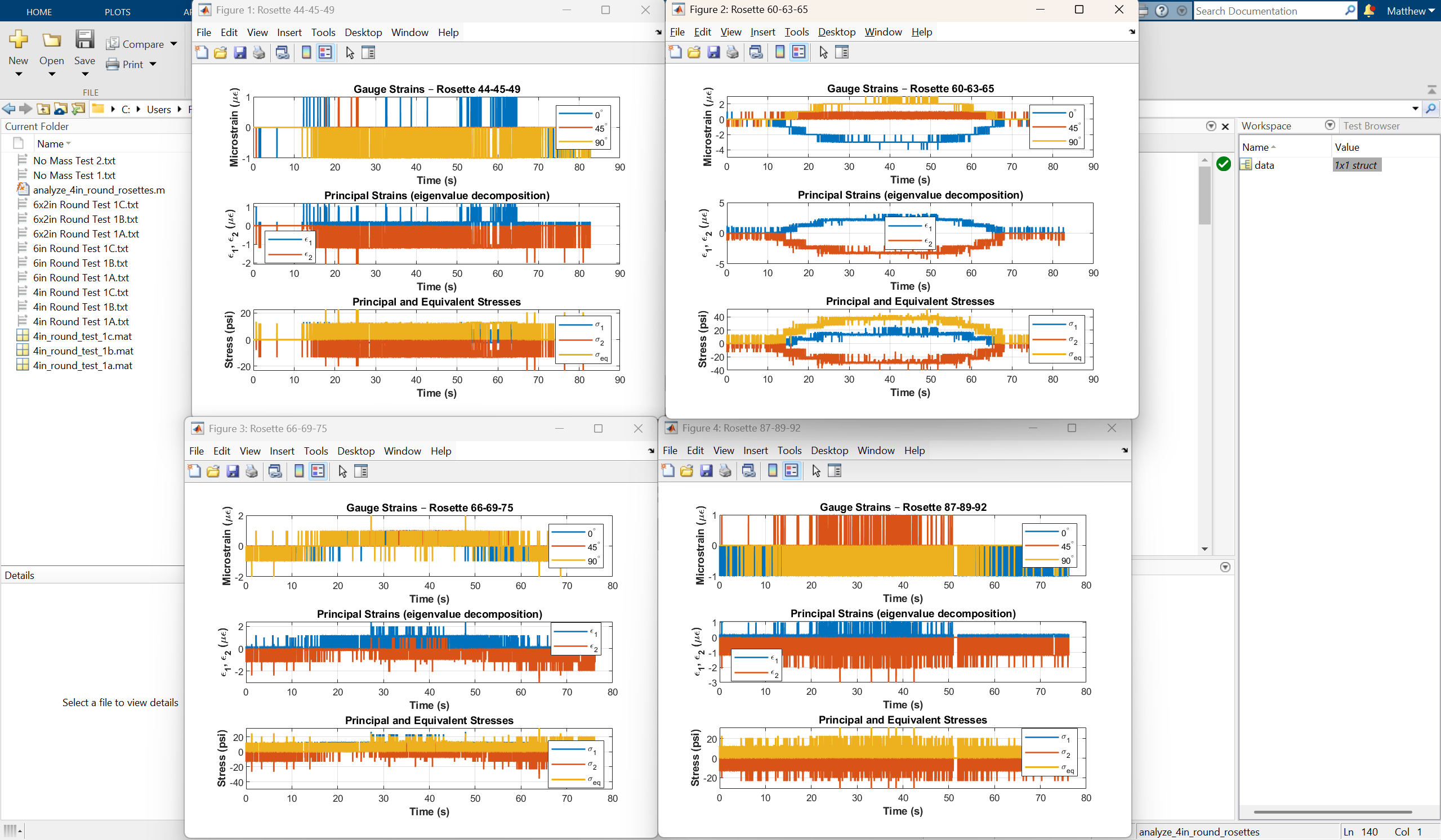
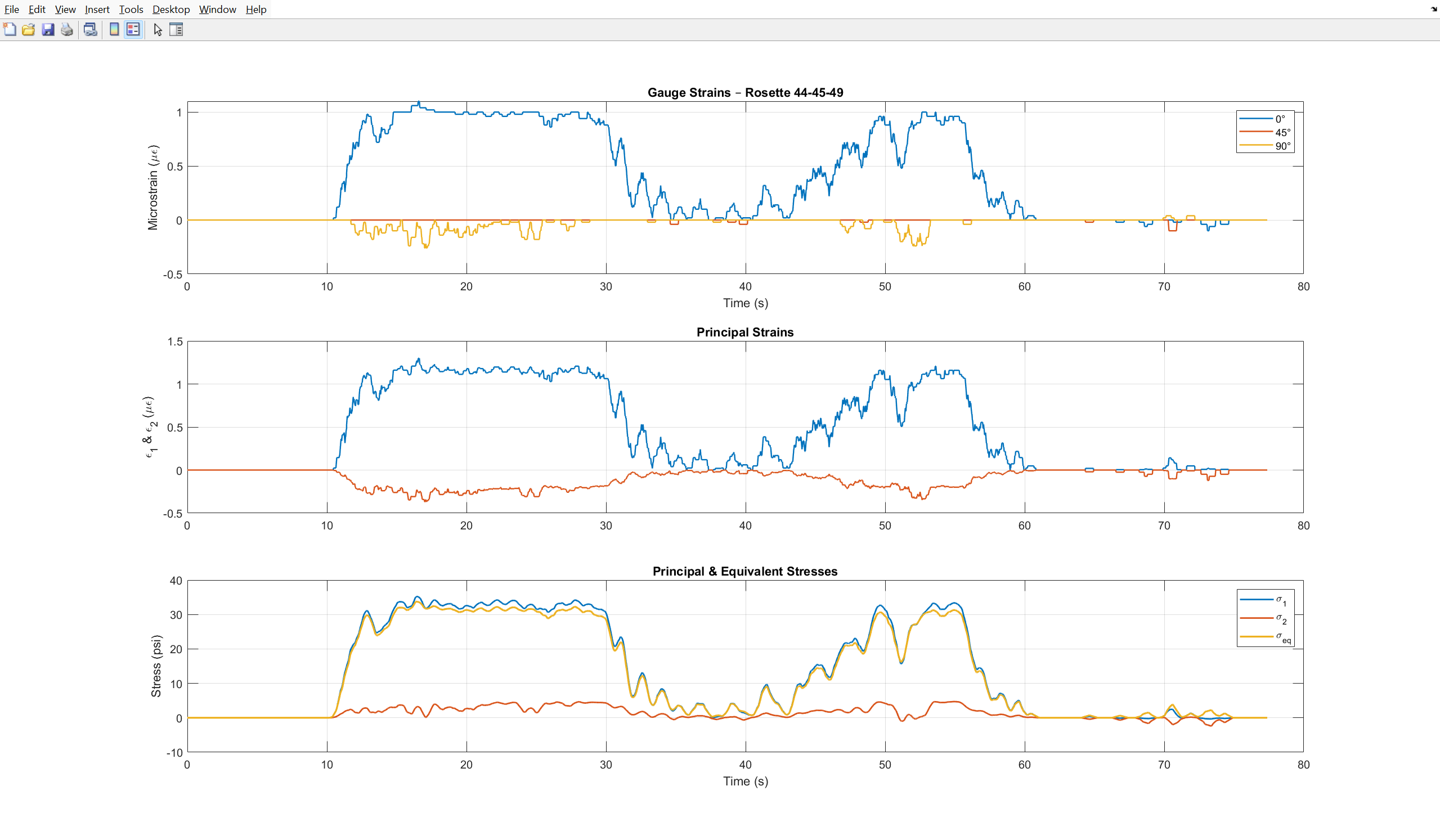
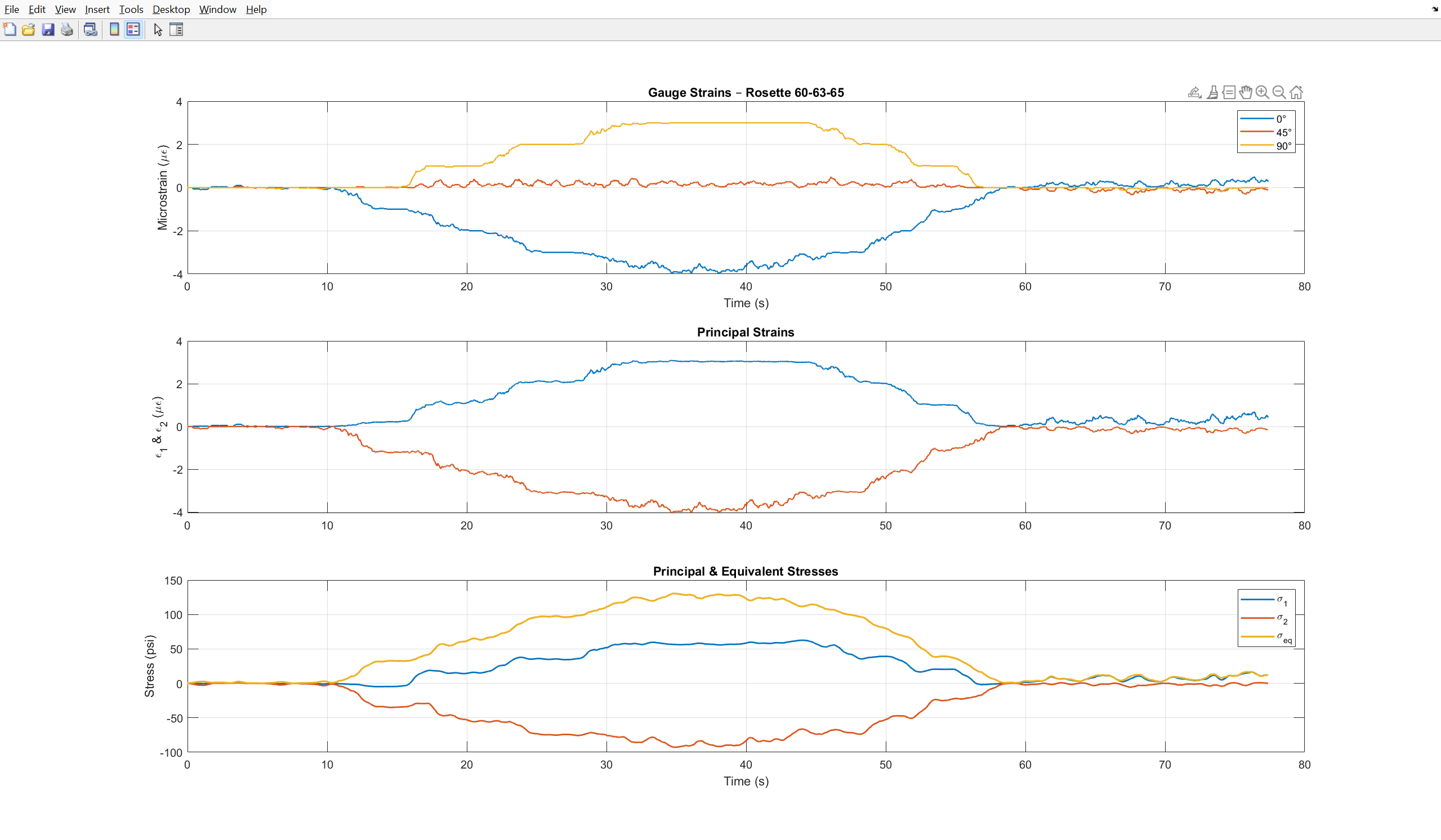
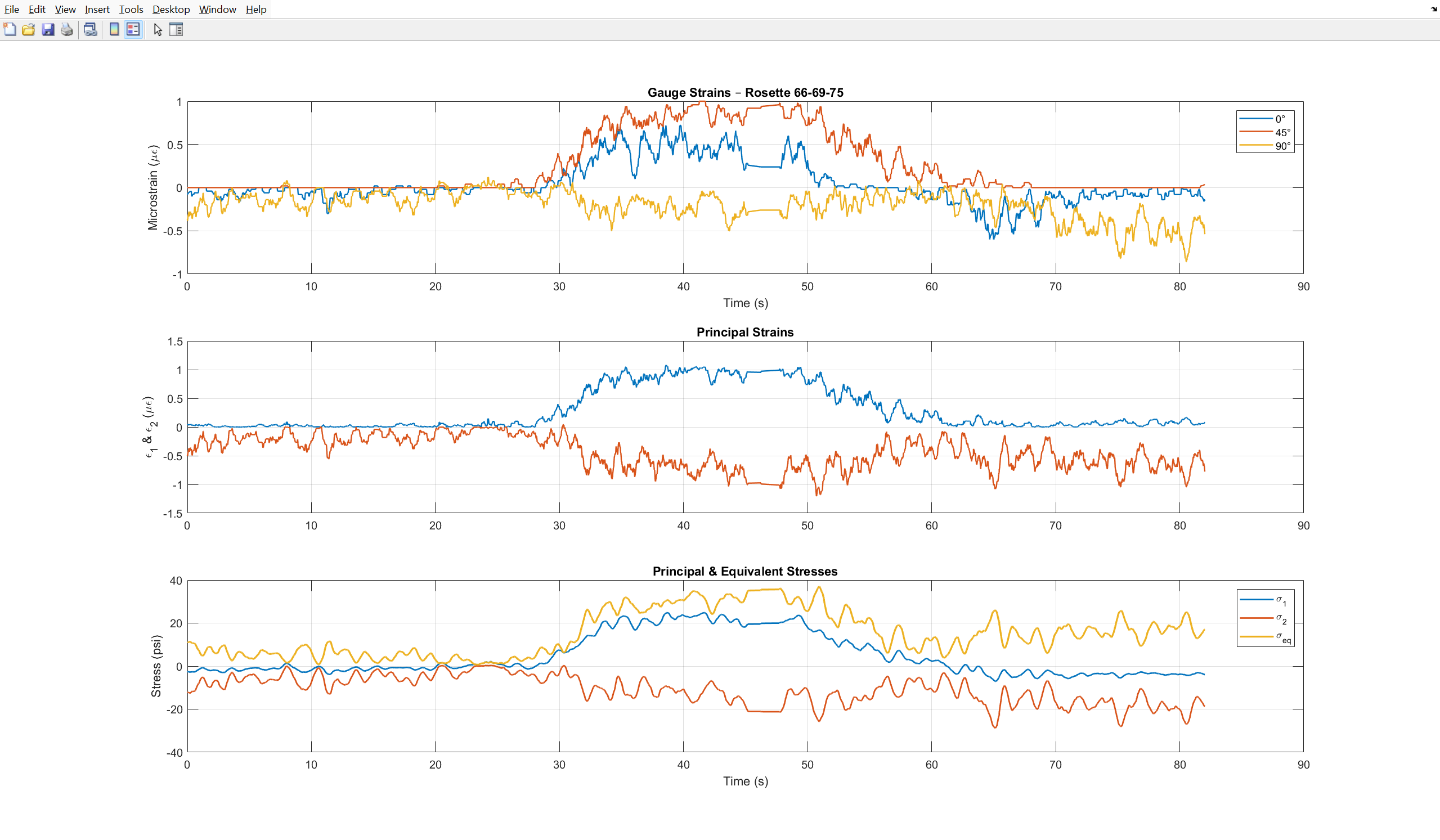
Cold Test Results
Hot Test
Poster