

In-Plane Shear Testing Sample and Fixture Development
Received President's Undergraduate Research Award for introducing a new specimen geometry for tube-extrusion material testing and designed a fixture capable of applying both torsional and axial loads.
Introduction
Most engineering metals are polycrystalline, meaning that a macroscopic piece of material is composed of many individual crystals, or grains. Within each grain, atoms are arranged in an ordered crystal lattice, and each grain can have a different crystallographic orientation relative to the overall part. Because deformation is easier along some crystallographic planes and directions than others, an individual grain is inherently direction dependent. In a polycrystal with nearly random grain orientations, these differences can average out, and the material may behave approximately isotopically.
Manufacturing processes such as rolling, drawing, forging, and extrusion, however, tend to rotate grains into preferred orientations, creating crystallographic texture. Once a strong texture develops, properties such as yield strength, ductility, hardening, and shear response can vary with loading direction. Processing history, grain texture, and crystallographic texture therefore play an important role in determining the anisotropy and asymmetry measured at the bulk scale.
Much of this directional behavior originates from the mechanisms by which crystals plastically deform. The most common mechanism is dislocation slip, which occurs along specific combinations of crystallographic planes and directions called slip systems. Whether a particular slip system activates depends on both the applied stress and the orientation of the grain. Two grains subjected to the same external load can therefore respond differently: one may be favorably oriented for an easy slip system and begin deforming plastically, while another remains relatively resistant.
The three most common metallic crystal structures—face-centered cubic (FCC), body-centered cubic (BCC), and hexagonal close-packed (HCP)—differ significantly in their available slip systems. FCC metals have 12 primary slip systems, allowing plastic deformation to occur relatively easily in many directions. BCC metals have 48 possible slip systems, although these are generally harder to activate because BCC crystals lack close-packed slip planes. HCP metals have only 3 primary basal slip systems that are readily activated at room temperature, with additional prismatic and pyramidal systems requiring higher stresses. As a result, HCP metals tend to show stronger directional dependence in deformation, especially when crystallographic texture is present.
When regular slip cannot easily accommodate deformation, the crystal can deform through twinning. Instead of atoms simply sliding past one another, a group of atoms shifts together in an organized way, causing part of the crystal to rotate into a new orientation. This changes how that region responds to later loading because different slip systems may become easier or harder to activate. As a result, twinning can change the material's strength and contribute to differences between its behavior in tension and compression.
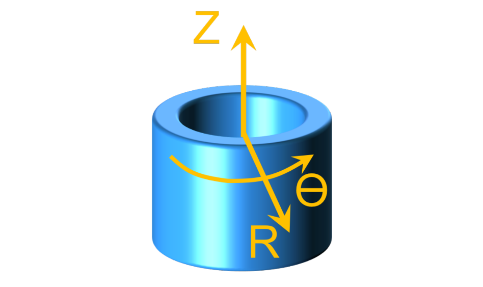
These effects make the characterization of processed tubular materials particularly challenging. A tube is naturally described using cylindrical material coordinates: Z, along the longitudinal or extrusion direction; θ, around the circumference; and R, through the wall thickness. The associated shear behaviors occur in the Z–θ, R–θ, and R–Z planes. Conventional mechanical testing, however, is much better established for materials described in Cartesian coordinates while equivalent methods are less developed for cylindrical coordinates. Conventional torsional loading of a tube primarily characterizes the Z–θ shear response, leaving the other cylindrical shear components unaccounted for.
A further complication is that conventional specimen preparation can disturb the very properties being measured. For transverse characterization of tubular material, ASTM E8 permits a ring to be removed from a tube, flattened, and then machined into a conventional tensile specimen. This procedure can change the anisotropy and asymmetry of the material through hardening or softening by activating slip, twinning, and residual stresses before the actual characterization test is performed. For materials whose properties depend strongly on crystallographic orientation and deformation history, this creates an important uncertainty in the measured data.
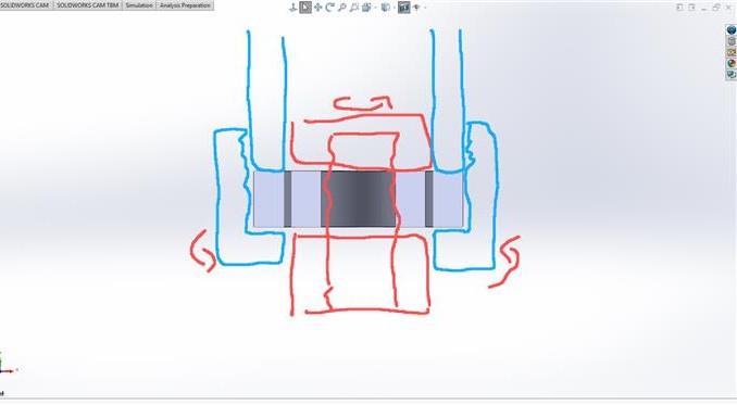
One potential solution is the Brosius twin-bridge shear geometry. The specimen consists of an inner circular region and an outer ring connected by two narrow shear bridges formed by tangential slots. Applying differential motion between the inner and outer regions concentrates deformation within these bridges. The twin-bridge arrangement was developed to create a controlled shear state while avoiding the unwanted moment produced by one-sided shear specimens and the averaging of oppositely directed shear zones that can occur in some symmetric shear configurations. Previous work on the Brosius geometry focused on flat sheet materials defined in Cartesian coordinates, rather than on specimens that preserve the natural cylindrical coordinate system of a tube. Adapting the geometry directly to a tube provides a possible route to characterizing shear with the original R–θ–Z material directions preserved. Differential rotation between the inner and outer portions of the specimen can generate R–θ shear, while differential translation can generate R–Z shear, creating shear states that conventional tube torsion cannot.
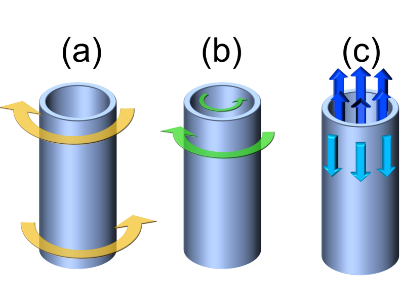
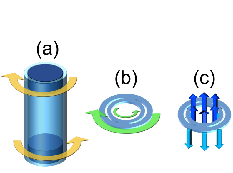
Therefore, the project’s goal is to modify the testing method so that it fits the geometry and material directions produced by manufacturing. Gaps remain in the mechanical testing of extruded tubes, and experimental and computational evaluation of differential inner-outer torsion and translation using Brosius geometry is needed. Successful validation of this approach could provide a more direct way to characterize cylindrical shear responses, improve calibration of anisotropic constitutive and yield models, and ultimately provide material-property data that more accurately represents the behavior of tubular components in their as-manufactured state.
Methodology
The first major decision was material selection. Candidate materials included magnesium, zinc, and titanium alloys because they can exhibit anisotropic behavior associated with low-symmetry crystal structures and processing-induced texture. The candidates were compared based on mechanical strength, availability in suitable tube extrusion sizes, availability, pricing, and machinability. Titanium-based materials were rejected since their relatively high strength would require either larger test loads or much smaller gauge sections that would complicate testing and specimen fabrication. Zinc was also considered because of its HCP structure and comparatively low strength, but suitable extruded tubing was difficult to source in the dimensions required. After contacting vendors and comparing available stock, AZ31B magnesium was selected because it provided the best combination of tube availability, relatively low cost, machinability, and a strength level practical for the intended experiments, also possessing the anisotropic and twinning-related properties of our interest.
Two specimen geometries were then developed from the same raw tube extrusion. The first was the adapted Brosius twin-bridge specimen machined from a short ring of the tube. The second geometry was a reduced-wall tube specimen intended for conventional torsional loading, included as a comparison case to the Brosius geometry. Simple torsion of a tube produces the Z–θ shear state, while the Brosius specimen produces R–θ and R–Z shear states. Testing both specimen types from the same extrusion therefore provides a common material baseline and allows the new geometry to be compared against an established loading condition.
To make this comparison meaningful, the reduced section of the torsion specimen and the combined area of the two Brosius bridges were designed to have the same effective shear area in their gauge regions. The gauge region volumes were also kept similar so that the amount of material participating in deformation could be comparable. Controlling area and volume reduces geometric differences and reinforces the comparison of resulting stress-strain responses. Another important design requirement was the radial location of the gauge material within the original tube wall. Both specimen geometries were designed to have their gauge regions at the midpoint between the original inner and outer surfaces to ensure that both tests characterize material from the same radial location. Because extrusion may produce variations in texture or microstructure through the wall thickness, doing this could reduce differences unrelated to the test geometry itself.
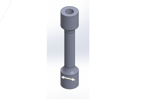
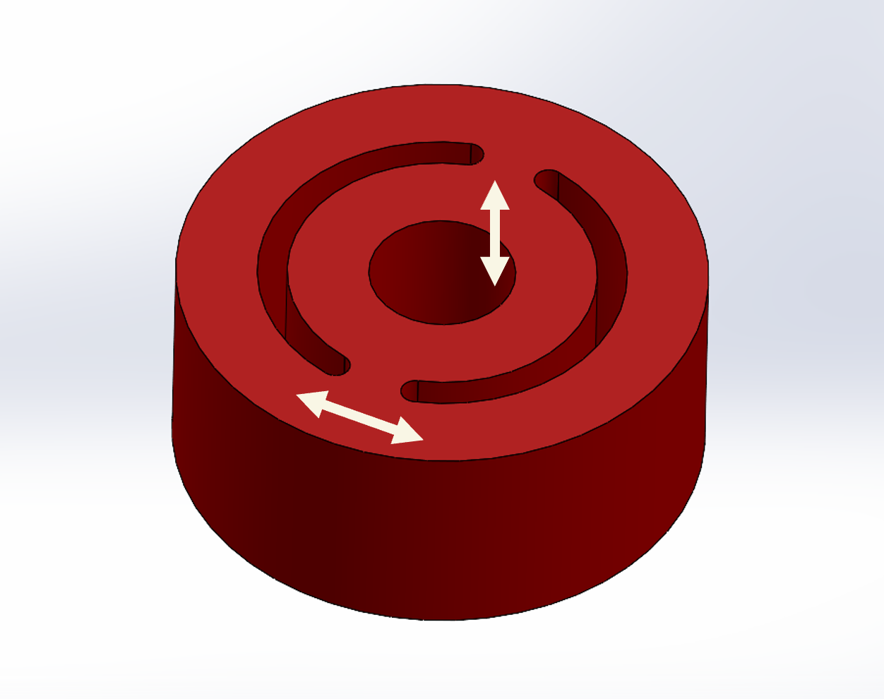
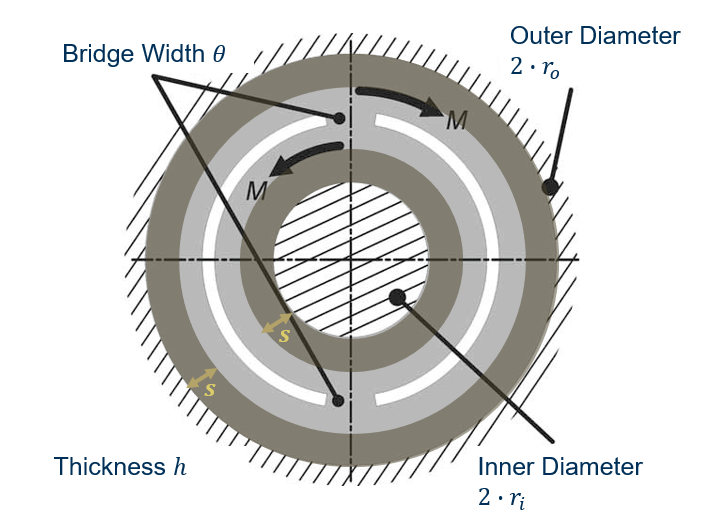
The experimental plan was organized around the three shear states of the cylindrical R–θ–Z coordinate system. The reduced-wall tube specimen would first be tested in torsion to characterize Z–θ shear. The Brosius specimen would then be tested in two modes. Relative rotation between the inner and outer regions would generate R–θ shear, while relative axial translation would generate R–Z shear. Loading would also be repeated in opposite directions—clockwise and counterclockwise rotation, or positive and negative translation—to investigate whether the shear response itself shows directional asymmetry. Strain measurement was planned to use Digital Image Correlation (DIC) so that specific deformation process of the shear bridges could be captured.
Sample Design
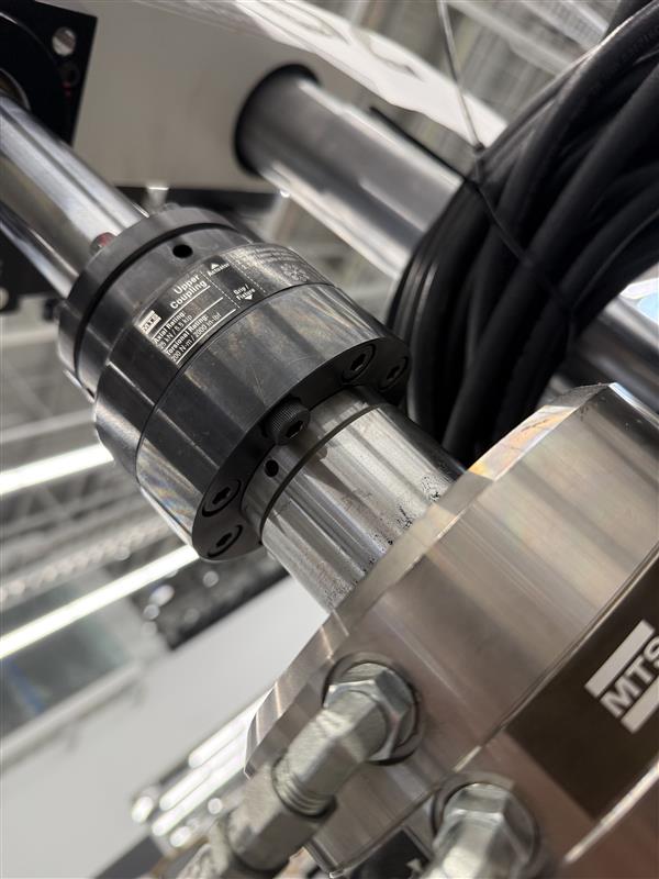
The sample geometry was developed around a small set of material, equipment, and manufacturing constraints. Testing was planned on an MTS Landmark 370.02 axial–torsional servohydraulic load frame equipped for simultaneous axial and torsional loading. The AMPF machine is nominally rated to approximately 25 kN axial load and 250 N·m torque, while the installed coupling shown on the machine is labeled 25 kN axial and 200 N·m torsional. Because the coupling is the more restrictive component in the actual test configuration, I used
as the practical design limits for specimen sizing. This ensured that the specimens could be brought to failure without exceeding the capacity of the installed hardware.
The raw tube was defined by its outer radius \(r_o\) and inner radius \(r_i\). For the Brosius specimen, \(h\) represents the axial thickness of the ring, and each shear bridge occupies a fraction
of the circumference. For the comparison tube specimen, \(s\) represents the amount machined symmetrically from both sides of the original wall: the outer radius is reduced to \(r_o-s\), while the inner radius is enlarged to \(r_i+s\). These quantities formed the principal geometric variables used in the sizing calculations.
The primary material constant was the estimated shear strength of AZ31B magnesium. Published values suggested a shear strength on the order of 130–145 MPa, but those values were not necessarily representative of the maximum stress that might be reached after strain hardening. For an ideal isotropic and symmetric material, axial and shear strengths scale approximately by a factor of \(\sqrt{2}\). Applying that relationship to the available tensile and compressive strengths suggested that shear strength could, in an upper-bound case, approach approximately 205 MPa. Because AZ31B is anisotropic and tension-compression asymmetric, and because pure shear may exhibit less hardening than axial loading, this value was treated as a conservative design estimate rather than an expected experimental result. I therefore used
for specimen sizing. This deliberately high design value ensured that the specimen geometry remained testable even if the actual material response was stronger than the lower published shear-strength range.
For the Brosius specimen under differential torsion, the total shear area of the two bridges is
The shear force at failure is \(F_s=\tau A_B\). Assuming that this force acts approximately at the mean tube radius,
the corresponding torque is
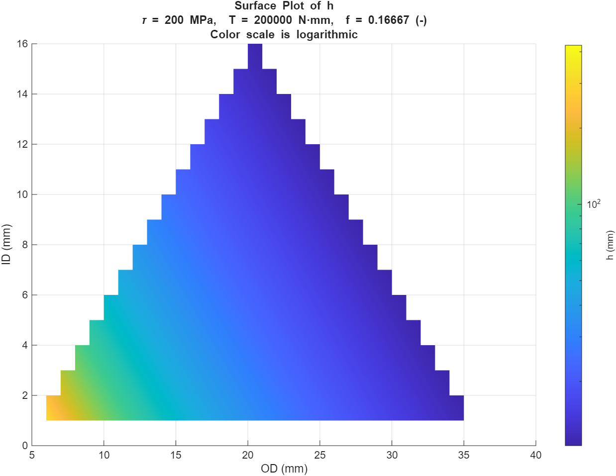
Solving for the required Brosius sample thickness gives
This equation directly connects the specimen thickness to the available torque, assumed material strength, bridge fraction, and raw tube dimensions. A larger tube increases the moment arm of the shear bridges and therefore permits a thinner specimen for the same failure torque, while a smaller tube requires a thicker shear region. This relationship was one of the main constraints used when exploring candidate tube sizes.
The reduced-wall tube specimen was designed as a comparison specimen, so its active shear area was intentionally matched to that of the Brosius specimen. After machining equally from the inner and outer surfaces, its gauge-section radii become
Its annular cross-sectional area is therefore
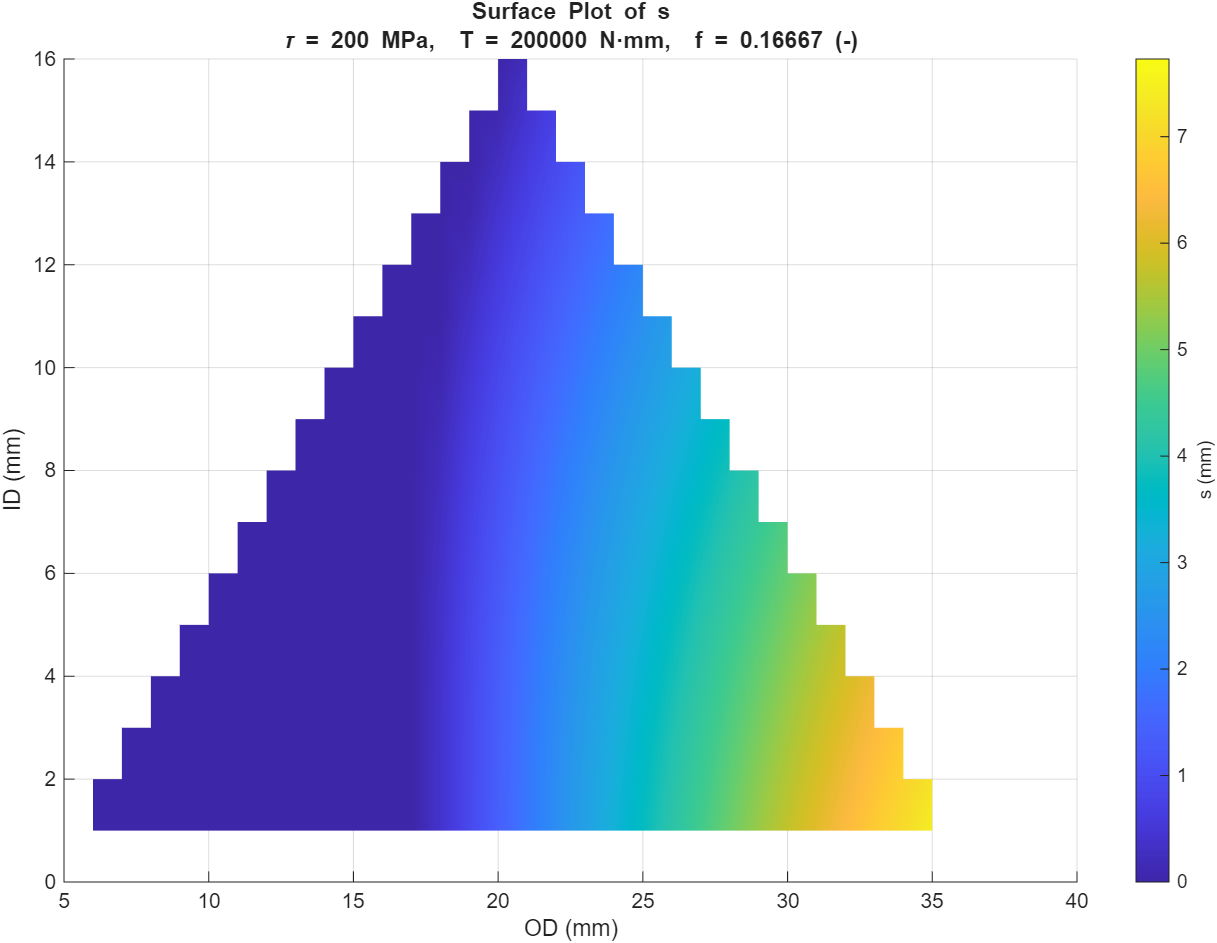
Setting this equal to the combined Brosius bridge area gives
which simplifies to
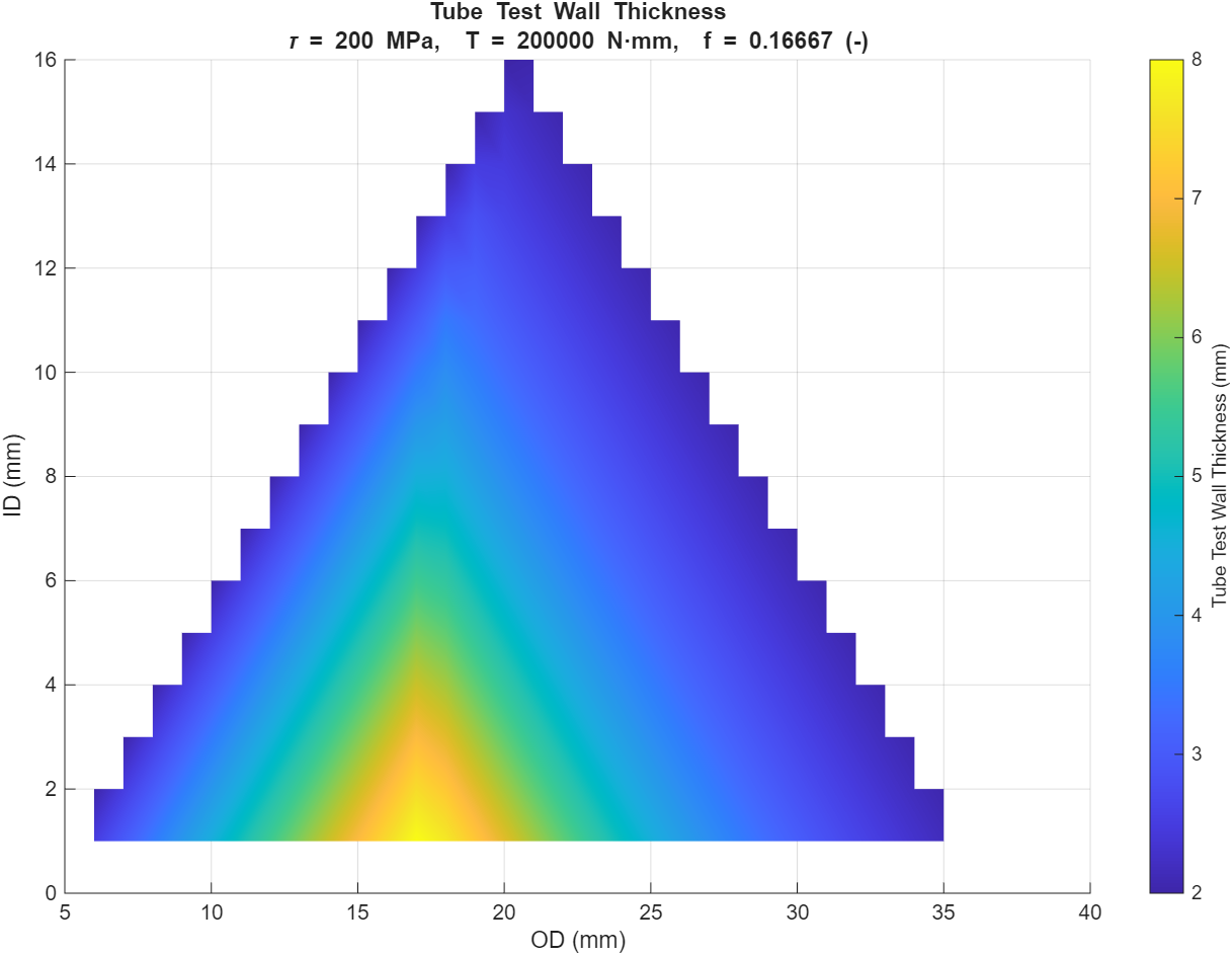
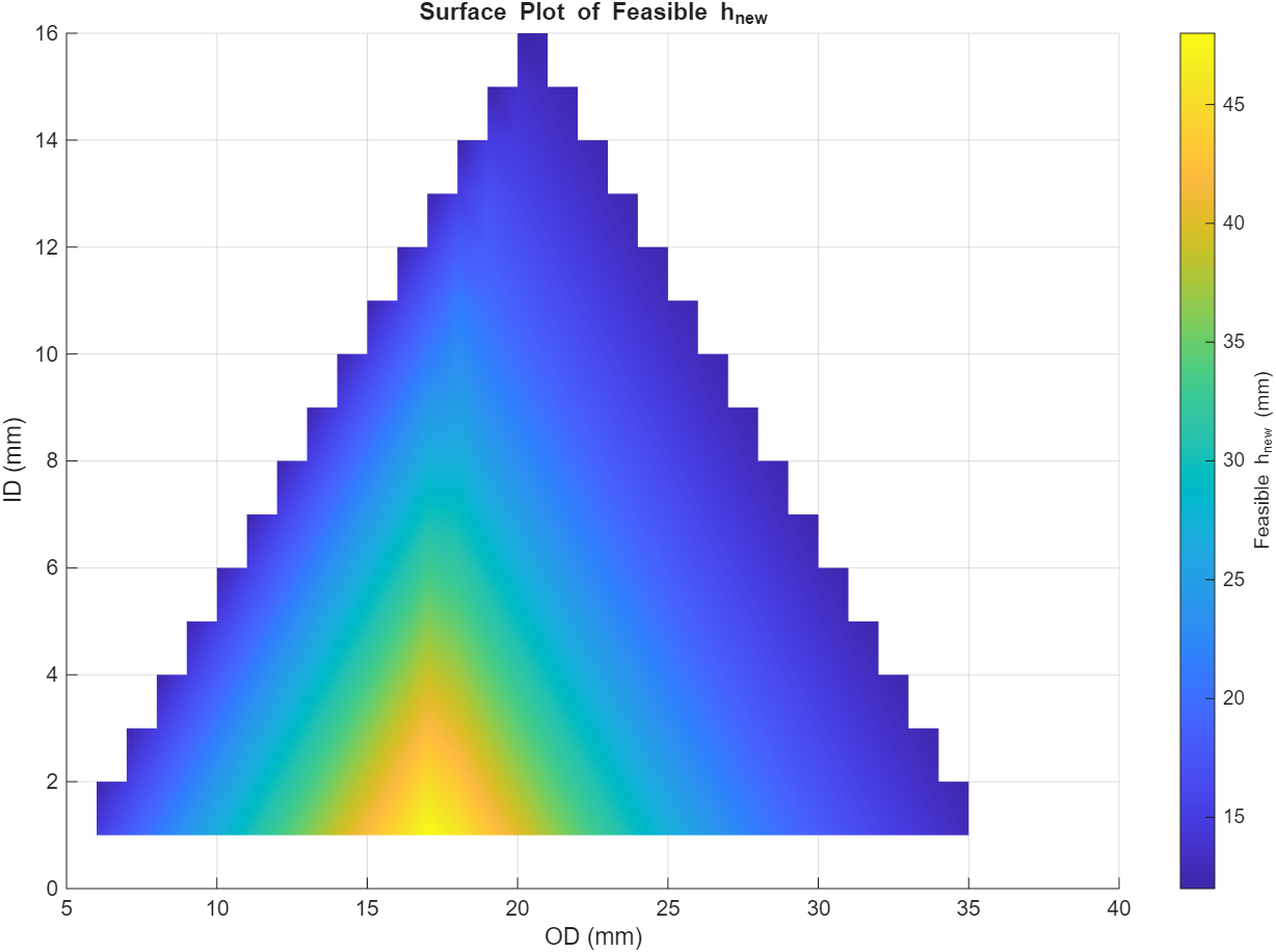
Combining this relationship with the torque equation allowed \(s\) to be solved for every candidate pair of \(r_o\) and \(r_i\). In other words, once a commercially available raw tube size was selected, the equations determined both how thick the Brosius ring should be and how much material should be removed from the comparison tube specimen. This kept the two specimens tied to the same material-strength and shear-area assumptions instead of sizing them independently. The MATLAB study treated \(r_o\) and \(r_i\) as the independent variables and calculated the corresponding \(h\) and \(s\) over the feasible design space.
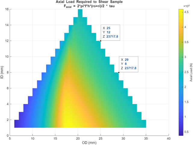
The geometry also had to remain suitable for the second Brosius loading mode: differential axial translation. Under axial loading, the same two bridges carry shear, so the force required to reach the assumed shear strength is
Every candidate geometry therefore had to remain below the 25 kN axial capacity as well as satisfy the torsional requirement. This was important because a specimen optimized only for torsion could otherwise require an impractically large axial force when used for R–Z shear testing.
Several manufacturing constraints further reduced the feasible design region. After machining, the comparison tube needed at least approximately 2 mm of remaining wall thickness,
so that the thin gauge section could still be machined reliably. The Brosius specimen also could not become so thick that its bridges would be susceptible to unwanted deformation modes or so tall and slender that axial loading could cause buckling rather than the intended shear failure. The remaining inner and outer regions also needed enough material for the fixture to grip without crushing the specimen. These geometric and manufacturing constraints were considered alongside the torque and axial-load equations rather than after the fact.
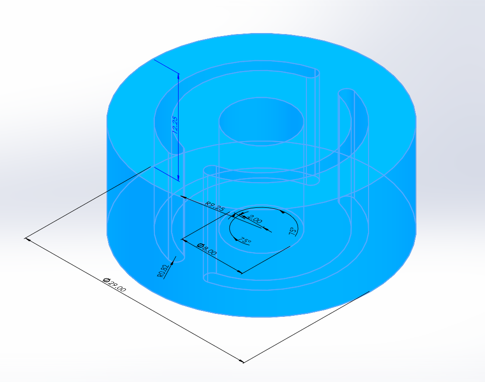
I implemented these relationships in MATLAB and evaluated the feasible design space across combinations of available tube inner and outer diameters. The plots made it possible to see how raw tube diameter affected Brosius thickness, required tube-wall reduction, remaining machinable wall thickness, and predicted axial failure load simultaneously. This converted the problem from manually checking individual tube sizes into a constrained parameter study. The final selected raw extrusion had an outer diameter of 29 mm and an inner diameter of 8 mm, providing a workable balance between test-machine capacity, machining limits, gauge geometry, and fixture engagement.
Fixture Design
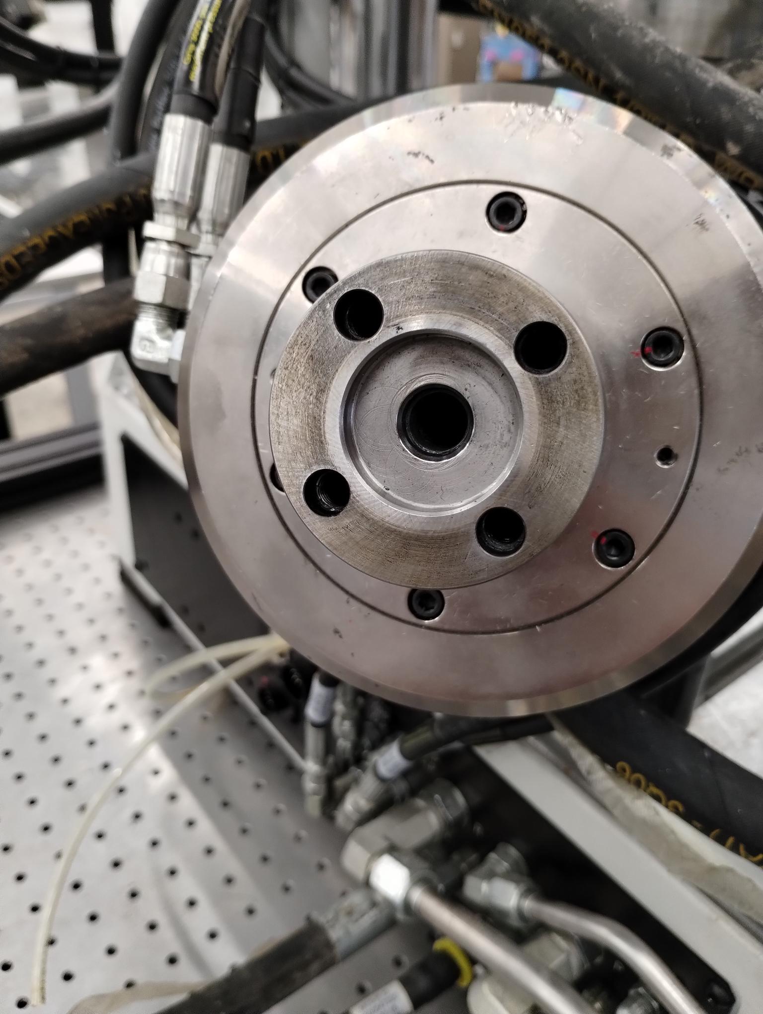
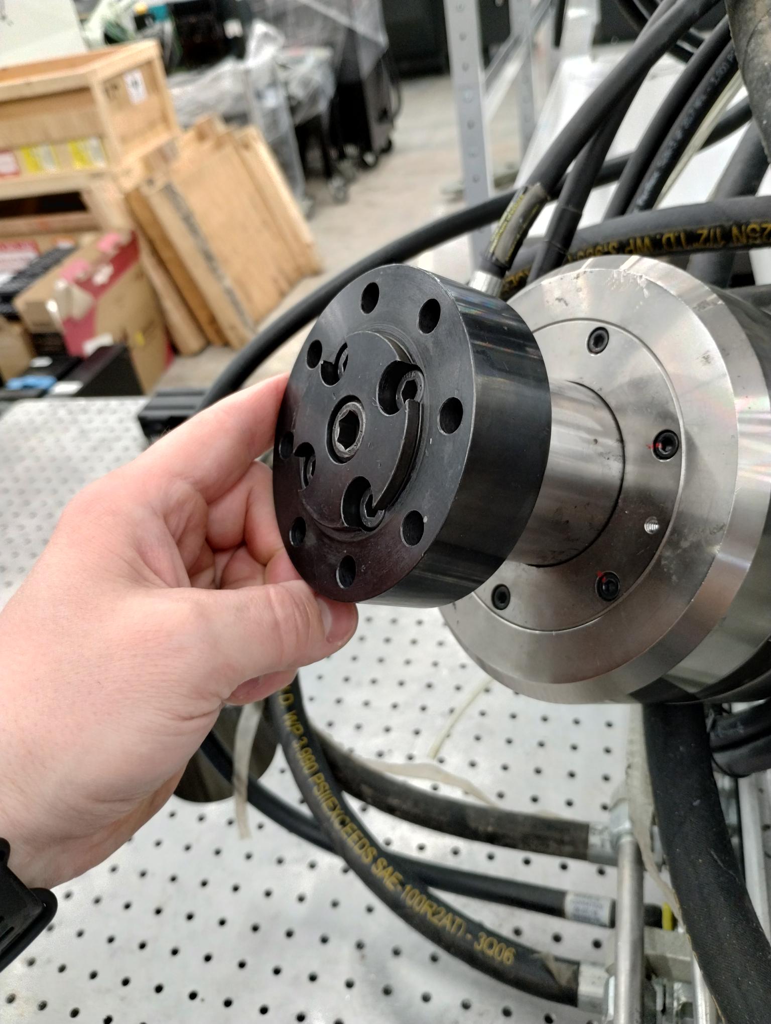
I proposed two similar fixture concepts. The first clamped onto the inner and outer rings of the Brosius sample using bolts and nuts, offering the clear benefit of simple installation. However, tightening the bolts could introduce a twist into the clamped regions. The second concept used latch locks, but a latch with a suitable shape and size for the inner ring was difficult to source. My partner proposed using two clamping pieces, but that approach risked deforming the sample even more than my first concept. Ultimately, the first concept was selected, with its twisting problem addressed by using a hand-held spacer between each nut and the sample during fastening.
The fixture faces contacting the sample were designed as knurled surfaces. In the initial sample-design calculations, I expected the radial shear torque to be transmitted by a simple friction force obtained by integrating a friction coefficient over the contact area. However, I could not find a reliable value for the exact friction coefficient in this situation. Using the best available estimate, approximately 0.2, the required clamping force would have squashed the sample before testing. I later realized that a knurled surface consists of many small pyramids. When pressed into the sample without crushing it, the upper limit of the friction force would be the force required to tear all of those pyramids away—ideally, the shear strength of the fixture material multiplied by the contact area. My mentors confirmed this idea. From that point forward, friction was no longer a design variable, which is why it is not discussed in the previous section.
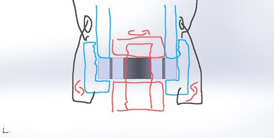
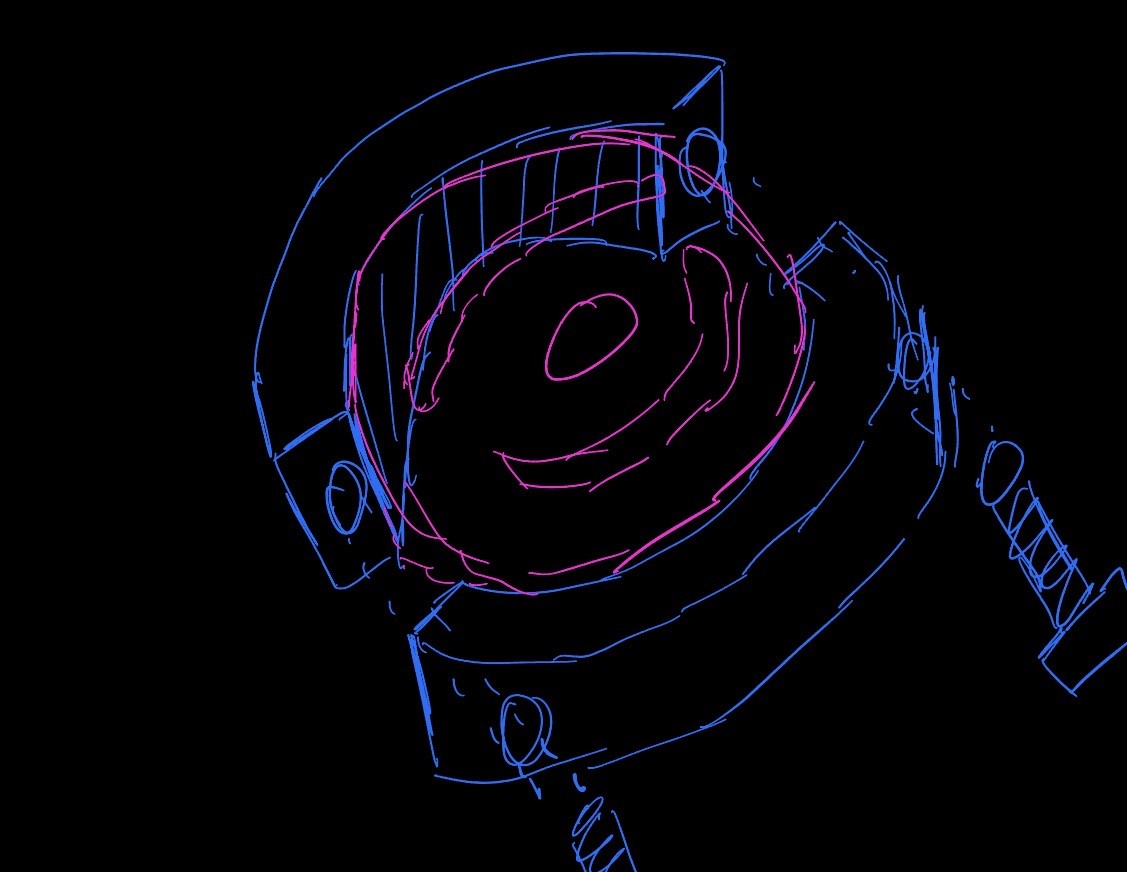
The first fixture design used the DIC manufacturer’s mirror mount, which produced an unnecessarily large body that was difficult to machine. In the next design, I began developing my own mirror mount. Since I was unsure which half of the fixture should carry the mirrors, I modeled mounts for both halves so I could discuss the options with my mentors. The mirror’s side might not be as smooth as its top, so the gauge-region image needed to be reflected without the mirror side in its optical path. The same constraint applied to the polycarbonate shield above the mirrors. I was also unsure whether silver or aluminum mirrors would be best, so I selected silver mirrors for their higher reflectivity. The thinnest available variant from the Georgia Tech-registered vendor was circular and 1/4 in thick, making the cut into the fixture so deep that the fixture could no longer support the applied torque.
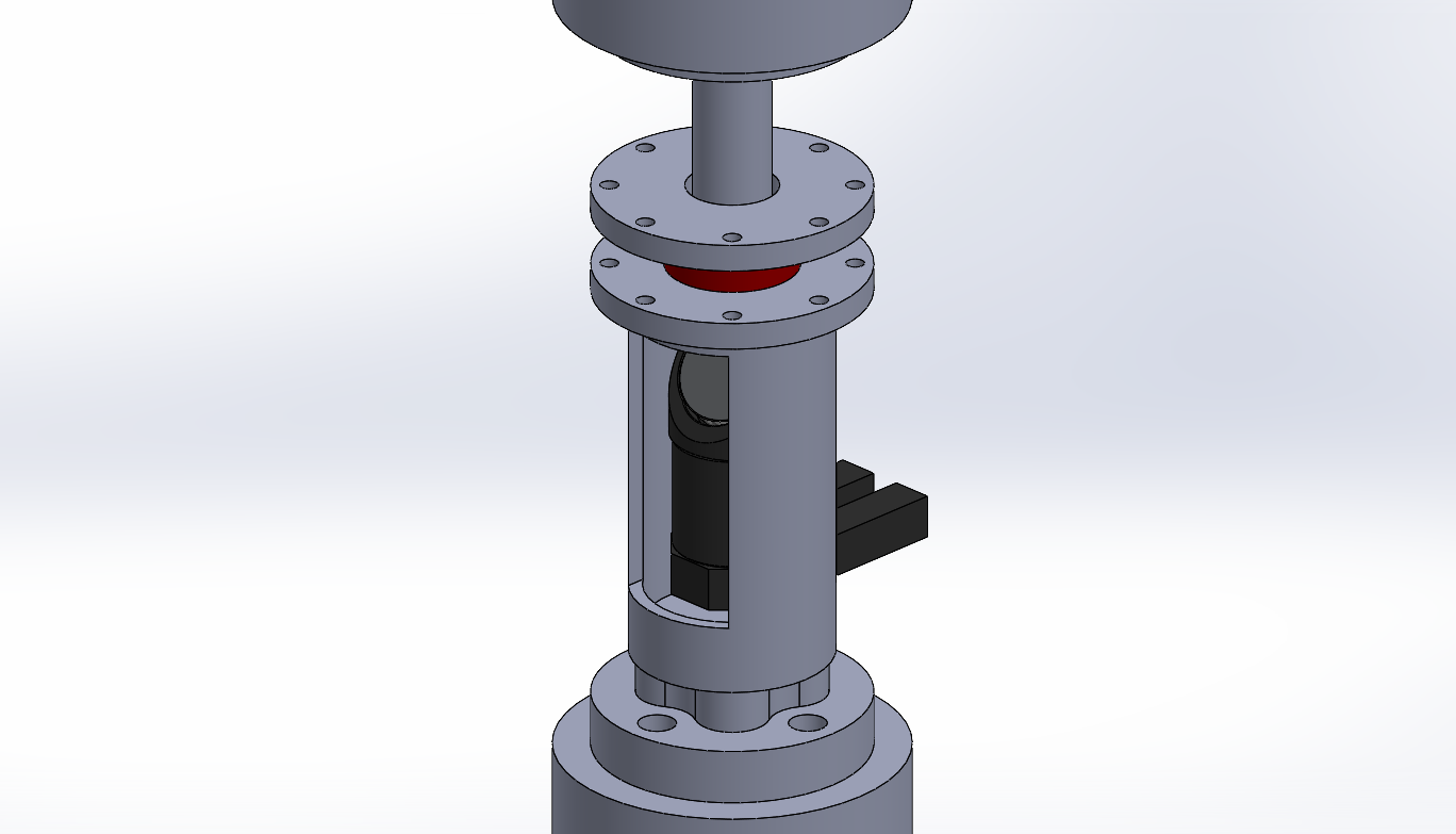
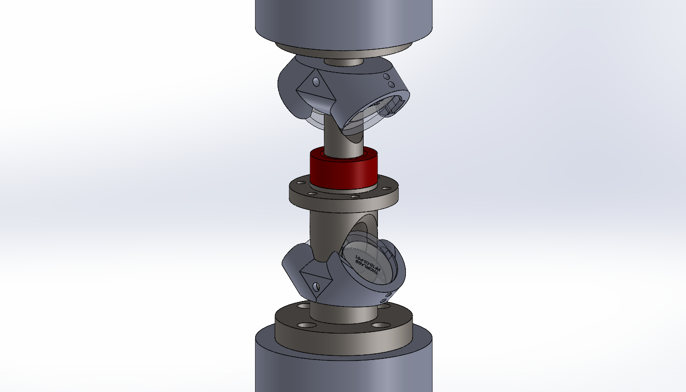
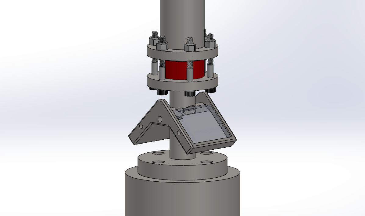
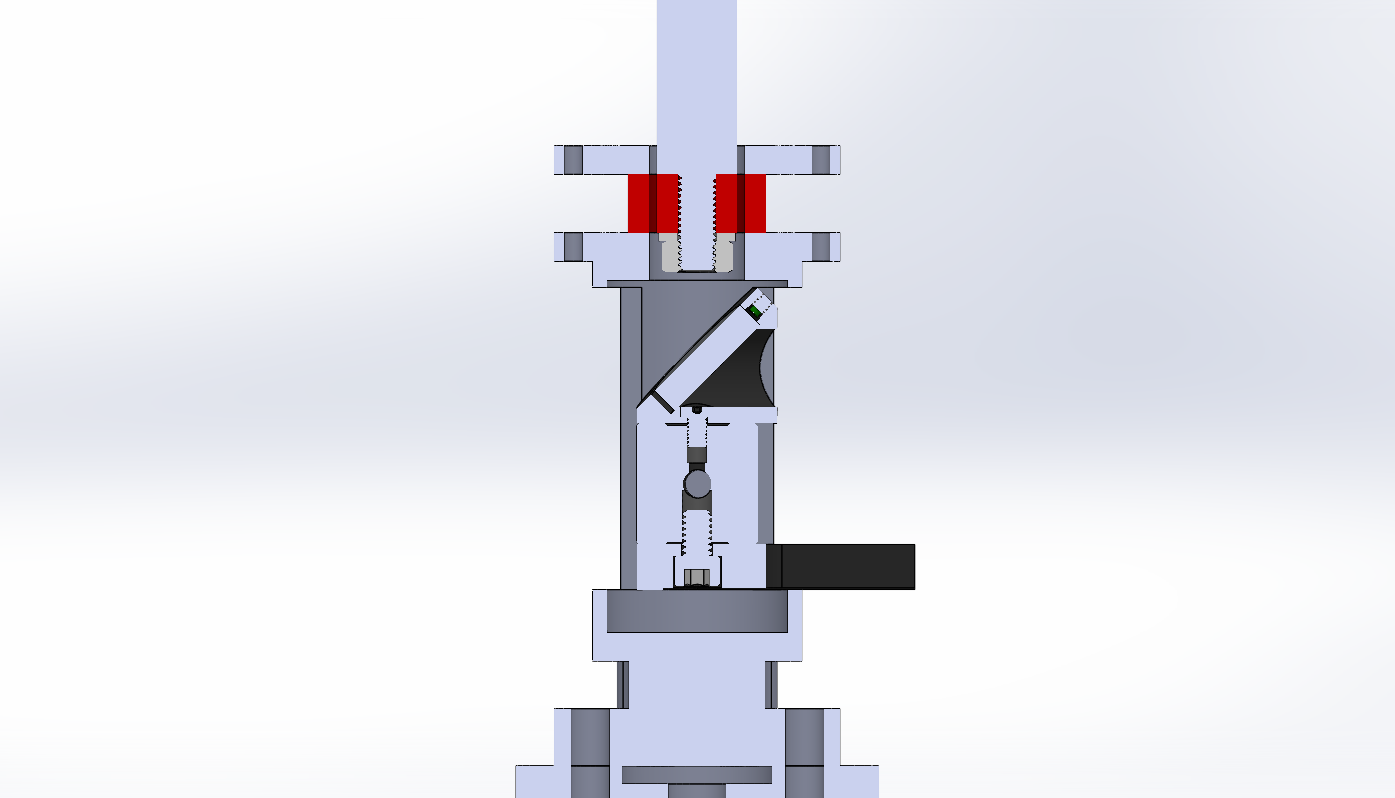
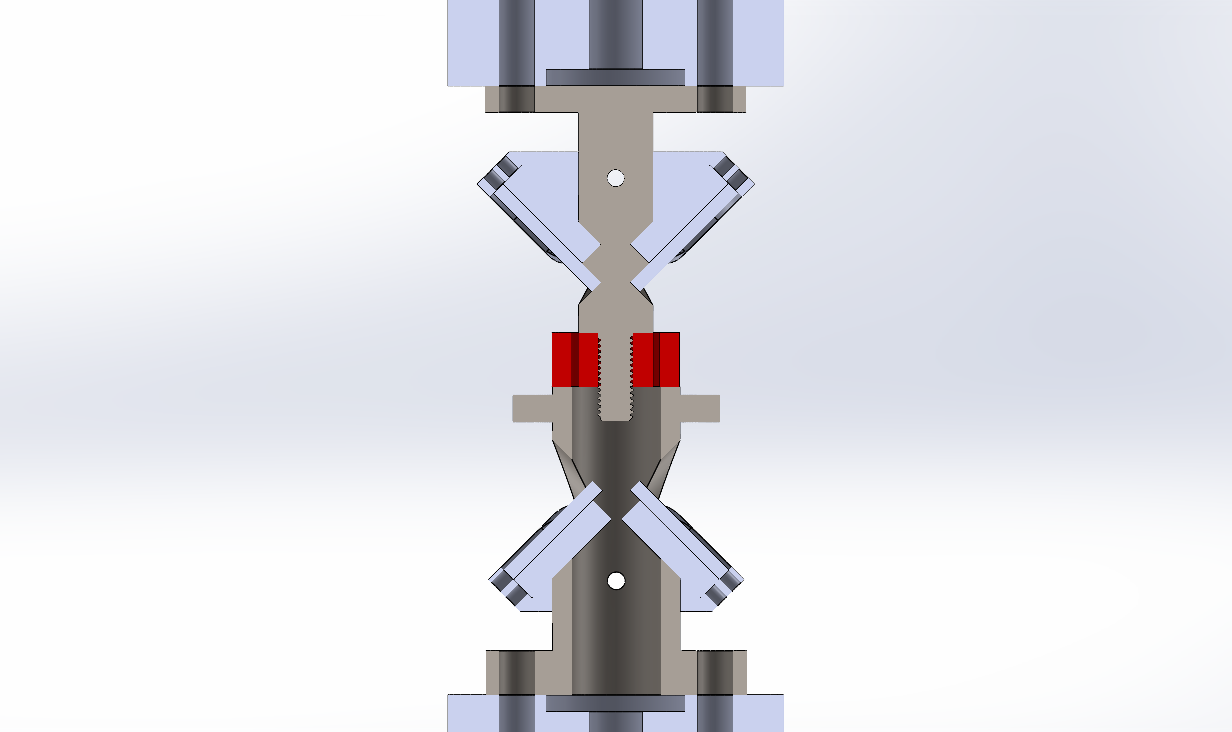
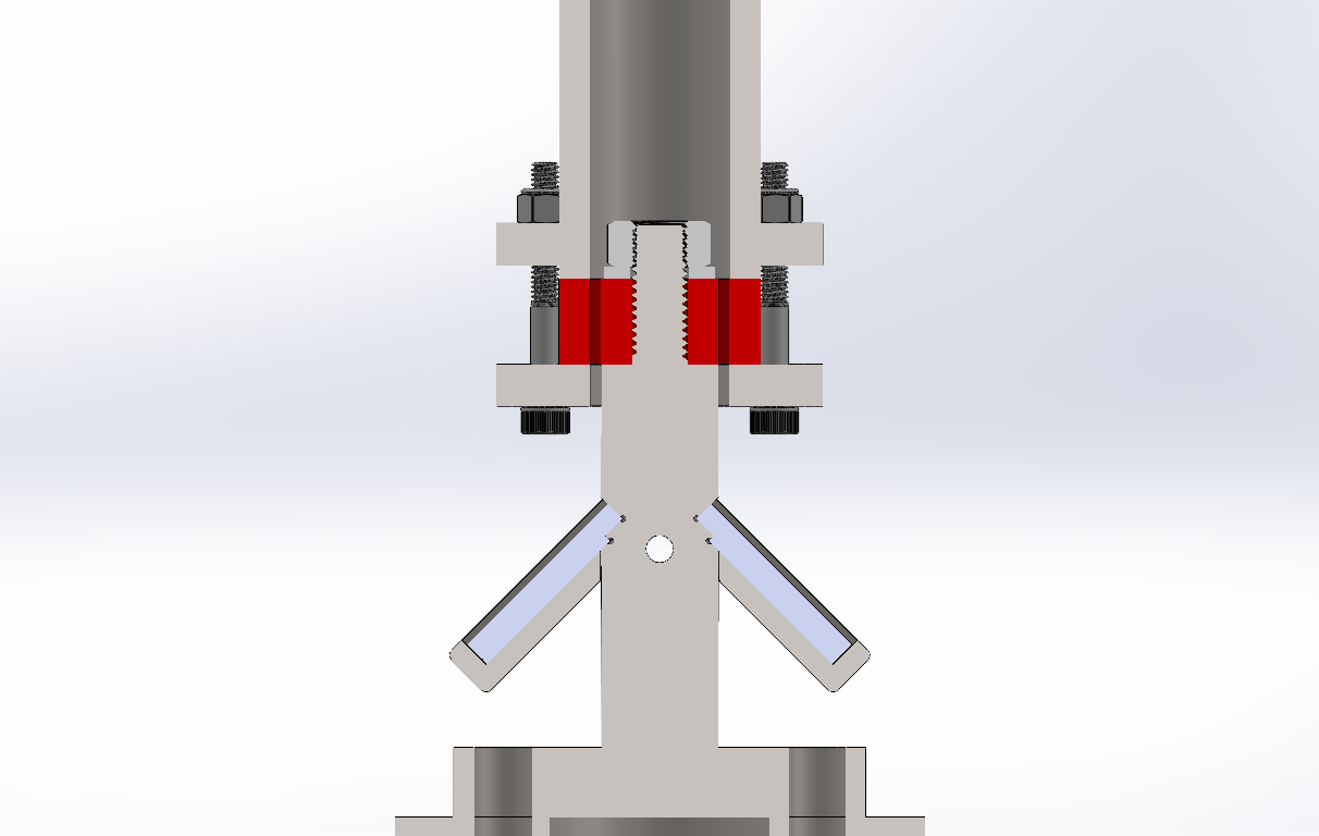
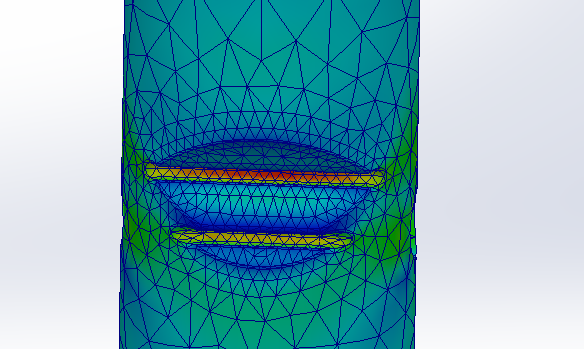
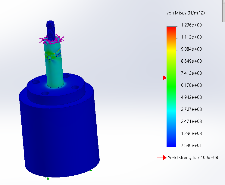
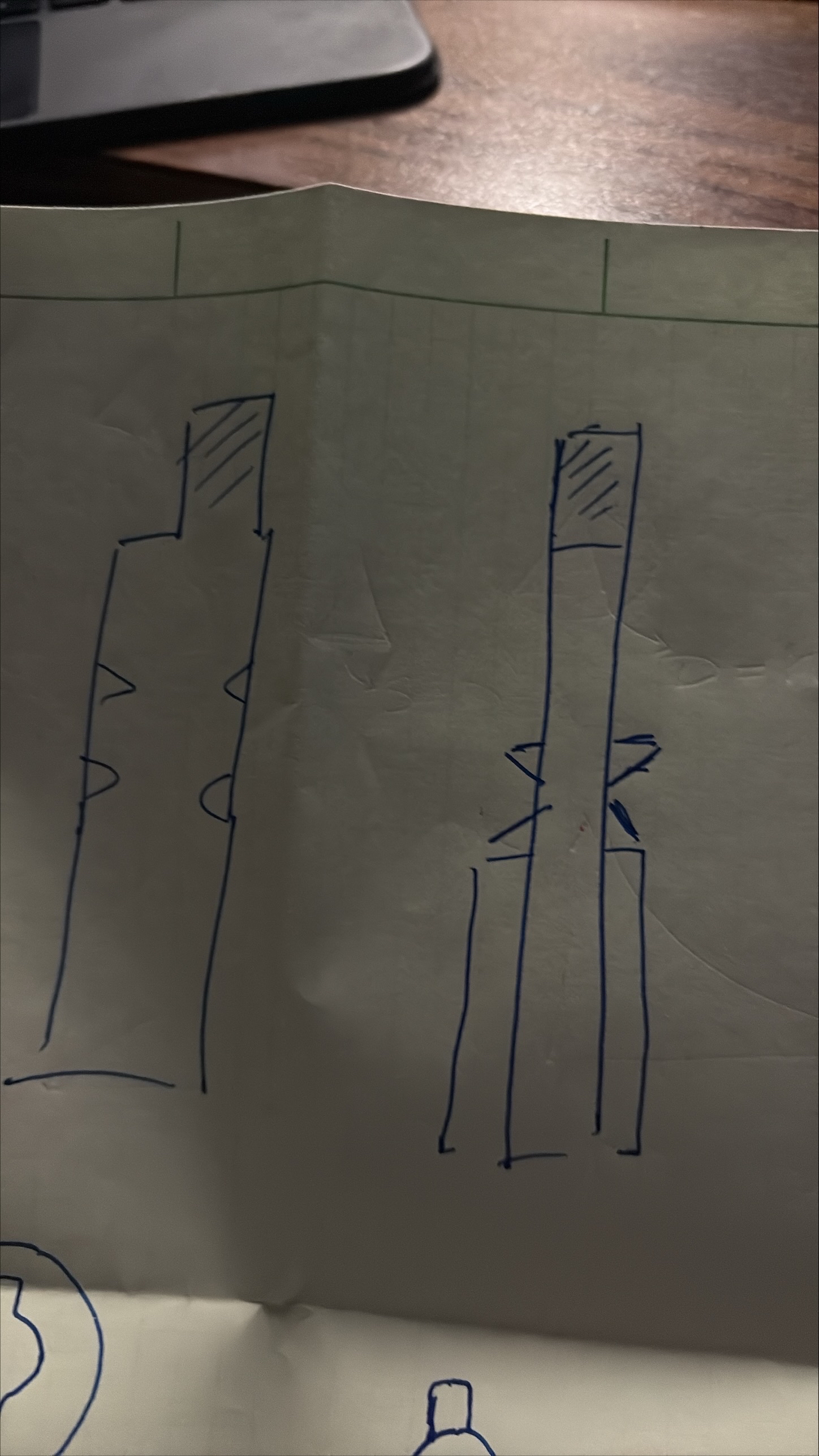
For the third design, my mentors confirmed that aluminum mirrors would provide sufficient reflectivity for this application, allowing me to use a thinner rectangular mirror. To facilitate FEA, reduce stress concentration, and provide more room for the mirror to bite into the fixture, I added corner-relief features to the mirror cuts. After running FEA and examining result convergence over a range of mesh sizes, I found that the stresses at the cuts were still high. This led to a new idea: split the fixture at the stress concentrator to “destroy” it, then mate the two pieces with a key-slot mechanism that could transmit torque without requiring excessive stress-relief geometry.
Results
As of May 2026, the project was paused at the fixture finishing phase due to a purchasing procedure problem with the AZ31B magnesium tube extrusion. Expect to continue in January 2027.
References
[1] Z. Brunson, “The Development of Novel Six-Dimensional Anisotropic and Asymmetric Yield Approaches Applied to the Study of Dwell Fatigue Using Various X-Ray Techniques,” Ph.D. dissertation, Dept. Mech. Eng., Colorado School of Mines, Golden, CO, USA, 2021.